IPC-4556 印制板化学镍钯浸金(ENEPIG)规范ENG.pdf - 第42页
APPENDIX 5 ENEPIG PWB Surface Finish Wetting Balance Testing Gerar d O’Brien, President S T and S Group. INTRODUCTION Consistent with all previous specification generations by the 4-14 Subcommittee for PWB surface finishes…
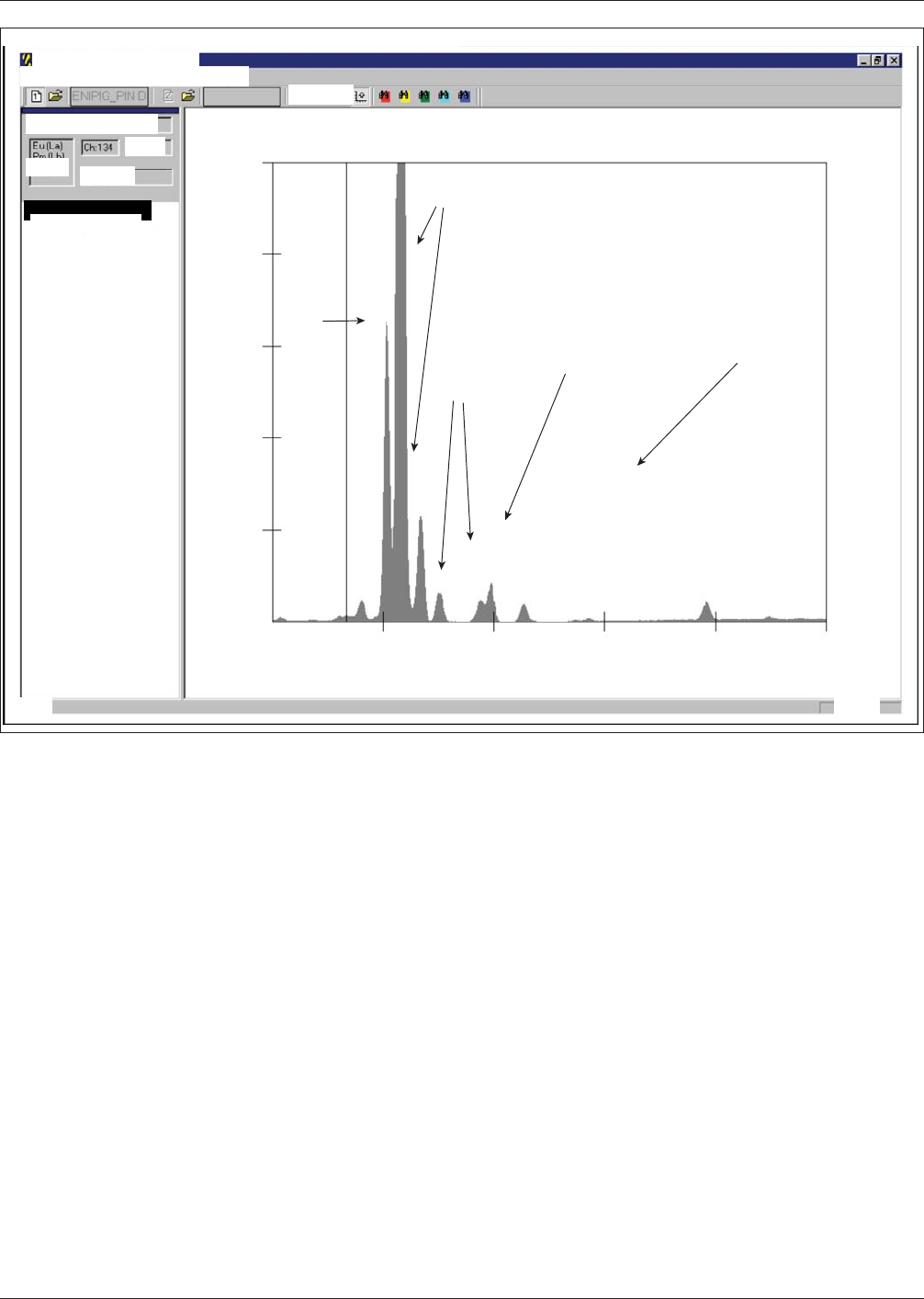
Above Figure A4-SS-4 shows typical ENEPIG plated on one ounce Cu/epoxy sample when measured with a pin diode detec-
tor. Note how Au L-β and Br K-α peaks are better resolved and the Au L-α peak is visible and distinct from Cu K-β, allow-
ing measurement of Au intensity without need for peak overlap corrections like peak deconvolution. Also note clear Pd peak
with low background noise.
Figure A4-SS4 XRF Spectrum of ENEPIG Plated on 1 oz Cu/Epoxy
ENEPIG pin diode.cts
2.7
16005
12804
C
9603
u
Ni
Au
Br
Pd
6402
3201
0
7.4 12.1
Count
KeV
s
16.8 21.6 26.3
January 2013 IPC-4556
Spectral Analysis Mode·WPHA
31
Ele Edt Yiew Display Ogerations BOl Help
FLE 1:ENIPIG_pin diode.cts
Kev5.9
Mn [Ka]
Cts 226.5
Peak (Ch.,KeV,Cts)
195,8.2,45653.2
△
Ready
L k
NUMI
APPENDIX 5
ENEPIG PWB Surface Finish
Wetting Balance Testing
Gerard O’Brien, President
S T and S Group.
INTRODUCTION
Consistent with all previous specification generations by the 4-14 Subcommittee for PWB surface finishes, solderability test-
ing using a wetting balance was performed to evaluate ENEPIG both in the ‘‘as received’’ condition and post temperature/
humidity stressing. There were six chemical suppliers who submitted samples for testing and because of their geographical
locations and the time needed to complete the plated test vehicles, some sample groups had significant ‘‘shelf life’’ prior to
testing of up to eight months. During this time, the samples remained in their original packaging.
Test Vehicle The 4-14 Subcommittee which works closely
with the 5-23A Task Group has settled on a wetting balance
coupon that has changed little over the last 5 years or so. The
latest iteration of the test coupon was built with 18 wetting
balance coupons and four ball shear coupons per array (see
Figure A5-1). The wetting balance coupon also contains the
NPL spread test vehicle, which was also used during the gen-
eration of this specification and retains through holes at the
opposite side (which were not used in these tests). The acid
copper plating and soldermask operations required to fabricate
these coupons were generously provided to the group by Mr.
Luc Beauvillier, who was then with Via Systems - Oregon.
Following extensive intra-committee discussions on the target thicknesses for the specification, it was proposed that initial
testing would be on samples plated to the following thickness requirements:
1) Electroless Nickel - 6 microns ± 1 micron
2) Electroless Palladium - 0.1, 0.2 and 0.3 microns nominally - no tolerance was set
3) Immersion Gold - the thickness would be ‘‘as supplied’’
4) Electroless Palladium at 0.5 microns nominal from two of the six suppliers, in order to evaluate a ‘‘heavy’’ palladium
Figure A5-1 Example of the Wetting Balance Coupon
deposit (see Table A5-1)
Six chemical suppliers took part by providing plated test vehicles:
1) Atotech
2) Dow Electronic Materials
3) Enthone
4) MacDermid
5) OMG
6) Uyemura (both U.S. and Japanese plated)
Used for the Testing of ENEPIG
Table A5-1 XRF Measurements of the Nominal 0.5 micron Electroless Palladium Samples
Supplier Identifier
Immersion Gold
Thickness (microns)
Electroless Palladium
Thickness (microns)
Electroless Nickel
Thickness (microns)
Target Thickness Per individual supplier 0.5 5 - 6
F 0.038 0.51 4.98
G 0.016 0.45 6.67
IPC-4556 January 2013
32
Some of these suppliers submitted ENEPIG samples that used
a phosphorus-containing reducing agent in the electroless pal-
ladium bath, whose deposits contain approximately 2 to 4
wt% phosphorus, while others submitted samples using other
non-phosphorus containing reducing agents, whose deposits
are sometimes classified as ‘‘pure palladium.’’ The samples
remained in their original packaging until the final ones had
been received for testing. This took some time in the case of
some suppliers and, when ready to commence the test, some
ENEPIG samples had 8 months of ‘‘natural’’ shelf life. Once
all samples were received, the packages were opened and each
group assigned a Roman numeral corresponding to a specific
nominal electroless palladium thickness and supplier - this
was marked on the edge rail of the array with an electric pen-
cil to avoid surface contamination of the plating. XRF read-
ings, using a PIN diode system with a measurement time of
sixty seconds, were generated for all sample groups. As can be
seen from the graphs (Figures A5-2 through A5-4), some of
the suppliers did not correctly measure the deposit at their
location, something that has been a major issue with the intro-
duction of ENEPIG. Additionally, one supplier chose to sub-
mit samples with two different immersion gold thicknesses.
The thinner of these two samples turned out to be of great
value to the committee, as it produced solderability failures
when stressed.
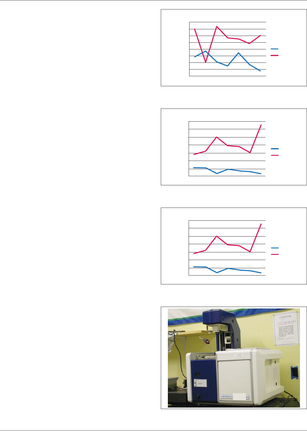
Solderability testing was performed on a Metronelec ST88
wetting balance (see Figure A5-5), using a solder bath for
coupon testing. Testing followed the requirements of the IPC
J-STD-003 B Solderability Standard and samples were tested
with both SAC305 and Eutectic SnPb solders. As per the stan-
dard, test temperatures of 255 °C and 235 °C were used for
the SAC305 alloy and the Eutectic SnPb alloy, respectively.
For the testing, a new charge of solder was used for each
alloy. Similarly per the Standard, Test Fluxes # 1 and # 2 were
used for Eutectic SnPb and SAC305 alloys, respectively.
The test coupons were removed from the array, the edges
carefully ‘‘wiped’’ over 1200 grit silicon carbide paper and
then wiped with a paper towel to remove any dust, to ensure
that no epoxy smear was present on the edge of the SMT pads
on the coupon that might prevent contact with the solder and
produce a false result.
Following coupon preparation, each coupon was immersed
into the appropriate flux for the alloy being used for five sec-
onds, excess flux being allowed to drain. The coupon was then
placed into a suitable tool holder and immersed to a depth of
0.5 mm at 90 degrees incident to the solder surface. A dwell
time of ten seconds was used for each coupon. Following the
test, the sample was inspected to confirm the wetting balance
results and the next coupon from that group run. Ten samples
per group were run for the ‘‘as-received’’ condition. Results
are shown in Figures A5-6 - A5-15.
IPC-4556-a5-2
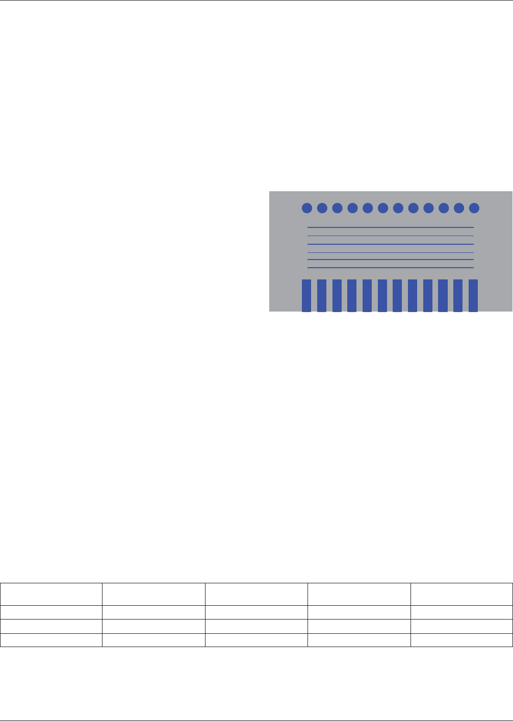
Figure A5-2 XRF Measurements of Gold and Palladium Thick-
nesses Supplied as Nominal 0.1 micron Electroless Palladium
0.1 microns Palladium
0.160
0.140
0.120
0.100
0.080
0.060
0.040
0.020
Gold
A
Palladium
0.000
microns
BCDEFG
IPC-a5-3
Figure A5-3 XRF Measurements of Gold and Palladium Thick-
nesses Supplied as Nominal 0.2 micron Electroless Palladium
0.2 microns Palladium
0.350
0.300
0.250
0.200
0.150
0.000
0.050
Gold
Palladium
0.000
microns
ABCDEFG
IPC-4556-a5-4
Figure A5-4 XRF Measurements of Gold and Palladium Thick-
nesses Supplied as Nominal 0.3 micron Electroless Palladium
0.2 microns Palladium
0.350
0.300
0.250
0.200
0.150
0.000
0.050
Gold
Palladium
0.000
microns
ABCDEFG
Figure A5-5 Metronelec ST88 Wetting Balance Used for the
Testing
January 2013 IPC-4556
33
maisc0