IPC-4556 印制板化学镍钯浸金(ENEPIG)规范ENG.pdf - 第81页
A second parameter that is obtained from the wetting balance test is the wetting rate. The wetting rate indicates the speed with which the molten solder meniscus climbs the coupon. Although this parameter is not used wit…
The metric of solderability was the contact angle, θ
c
. The lower the contact angle, the better is the solderability. The value
of θ
c
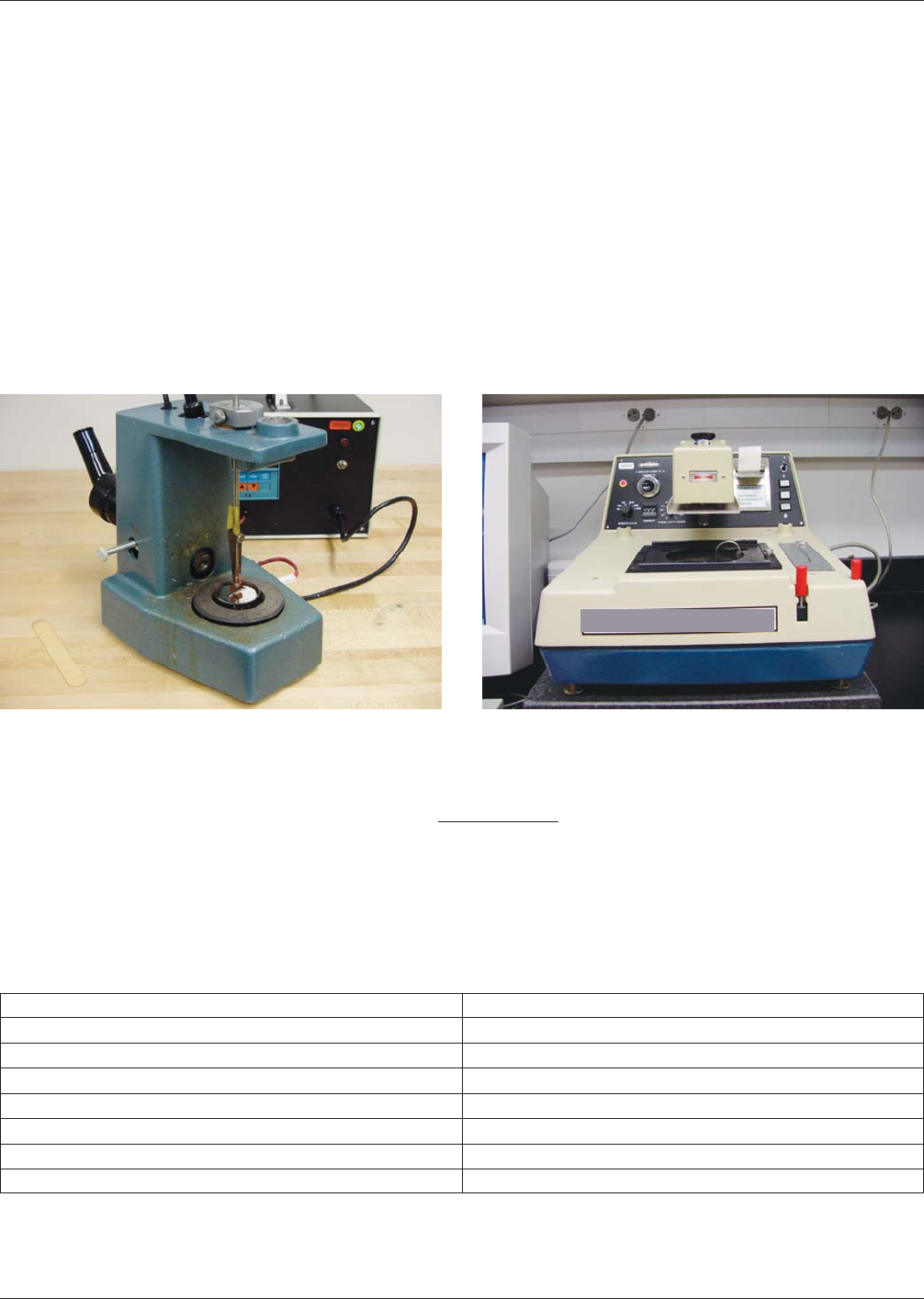
was determined by the combination of two test methods. The first method is the meniscometer test. This test measures
the meniscus height, H, or vertical movement of a solder meniscus up the side of the coupon, using a traveling microscope
(Figure A11-1a). Five trials were performed per each test condition. A mean value for H and standard deviation were deter-
mined from those tests.
The second test method utilized a wetting balance (Figure A11-1b) to measure the weight of the meniscus that forms on the
coupon. Five separate tests were performed with this technique. The meniscus weight was described by the mean of those
five values and one standard deviation. When the flux-coated coupon is immersed into a solder bath, initially an upward
force is exerted on the sample. The upward force is caused by (a) the solder displaced by the sample volume plus (b) the
solder that is displaced by the nonwetting or ‘‘negative’’ meniscus prior to the start of the wetting action. As wetting and
spreading of the molten solder progresses up the coupon, the negative meniscus is lost, and the solder then generates a down-
ward force because of its weight. However, the buoyancy force is not lost; it remains pushing up on the coupon and, as
such, must be taken into account when calculating the net force or weight, w, of the molten solder meniscus on the coupon.
Once these measurements have been obtained, the value of θ
C
, is calculated using Equation 1, where ρ is the solder den-
sity, g is the acceleration due to gravity, P is the sample perimeter (cm), and H is the meniscus height.
θ
c
= sin
−1
[
4
2
w −
(
pgPH
2
2
4w
2
+
(
)
pgPH
2
)
2
]
Equation 1
In general, solderability is considered good-to-excellent for electronic and structural applications when the value of θ
C
is
less than 30 °. Solderability is adequate as long as θ
C
remains less than 50 ° as has been validated by the use of Pb-free
solders on printed wiring assemblies [3,4,5,6]. A more inclusive guideline is shown in Table A11-1 [7].
Figure A11-1a Meniscometer Figure A11-1b Wetting Balance
Table A11-1 ‘‘Relative Wettability Guideline,’’ Using Contact Angle (θ
C
) As ‘‘General’’ Metric
Relative Wettability Contact Angle (θ
C) Range
Perfect 0° < θ
C
<10°
Excellent 10° < θ
C
<20°
Very Good 20° < θ
C
<30°
Good 30° < θ
C
<40°
Adequate 40° < θ
C
<50°
Poor 55° < θ
C
<70°
Very Poor 70° < θ
C
IPC-4556 January 2013
70
MULTICORE SOLDERS

A second parameter that is obtained from the wetting balance test is the wetting rate. The wetting rate indicates the speed
with which the molten solder meniscus climbs the coupon.
Although this parameter is not used within industry standards, testing at Sandia National Laboratories has determined that
it provides a correlation between the laboratory test and performance in fielded processes.
Test Results - Contact Angle, θ
C
The contact angle data for Vendors 1 and 2 are plotted in Figure A11-2 as a function of
the exposure time in the Battelle Class 2 environment. If the actual storage environment is a Class 2 environment, the fol-
lowing correlation between the accelerated test exposure time and the actual storage lifetimes is as follows:
• 8.4 hrs corresponds to ~ 3 months;
• 33.6 hrs,~1yr;
• 168 hrs, ~ 5 yrs; and
• 336 hrs, ~ 10 yrs.
It is clear that, the ENEPIG finishes, used in conjunction with the Sn-Pb solder and RMA flux, exhibited excellent solder-
ability that was not degraded by even the longest exposure to the Class 2 conditions. In fact, the contact angles of the Ven-
dor 1 finish actually decreased slightly after exposure to the Battelle Class 2 conditions. Although both ‘‘thick’’ and ‘‘thin’’
variants from Vendor 2 have only been aged for 168 hours (~ 5 yrs), the contact angles remained very low and unaffected
by the Class 2 exposure. More importantly, it is also apparent that the two Pd thicknesses of these ENEPIG finishes pro-
vided comparable solderability performances, which opens the door to using the less-expensive, thinner Pd layer.
IPC-4556-a11-2
Figure A11-2 ENEPIG with Thin and Thick Pd from Vendors1&2–Contact angles as a function of Battelle Class 2 aging using
Sn63Pb37 solder, RMA flux and 245 °C max. temperatures.
0
5
10
15
20
25
30
35
40
ENEPIG Sn63-Pb37
245C
Contact Angle Vendor 1 Thick Pd
Contact Angle Vendor 2 Thin Pd
Contact Angle Vendor 2 Thick Pd
Aging Time (hrs)
Contacr Angle (º)
January 2013 IPC-4556
71
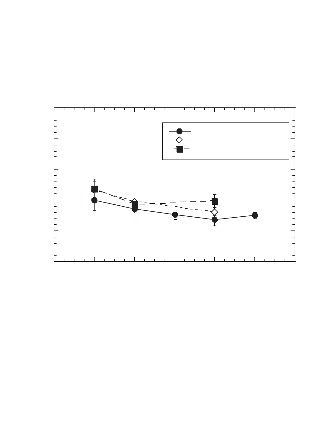
Test Results - Wetting Rate (W
R
) The wetting rate behavior was also assessed for these finishes. Generally speaking, there
were only small decreases in the wetting rate as a function of increased aging time in the Class 2 environment. The same
trend was observed across all three candidate ENEPIG finishes (Figure A11-3). Auger Electron Spectroscopy (AES) was
used to determine the source of the slower wetting behavior. The primary cause was attributed to a small amount of Pd that
had diffused through the Au to the surface. The driving force for that diffusion is a combination of the elevated temperatures
and oxidization potential established by the air environment above the sample. The Pd proceeded to oxidize, thus, slowing
the wetting and spreading process. A secondary factor may be a slight buildup of carbon compounds detected by AES on the
Au surface. The small decreases in wetting rate would not impact an actual manufacturing process.
IPC-4556-a11-3
Figure A11-3 Wetting Rate as a Function of Battelle Class 2 Aging – Both vendors1&2using Sn63Pb37 solder, RMA flux and 245
°C max. temperatures.
Wetting Rate (mN/sec)
0
20
40
60
80
100
As Fabricated 8.4hrs 33.6hrs 168hrs 336hrs
ENEPIG Sn63-Pb37
245C
Wetting Rate V1 Thick Pd
Wetting Rate V2 Thin Pd
Wetting Rate V2 Thick Pd
Aging Time (hrs)
IPC-4556 January 2013
72