ELA Installation.pdf - 第13页
SAFETY FE ATURES PRINTHEAD COVERS Chapter Issu e 3 Jun 01 Installati on Manua l 2.3 PRINTHEAD CO VERS Access to the machine printhe ad is achie ved by ra ising the shutte r at the front of the machin e. Access to the ste…

SAFETY FEATURES
EXTERNAL EMERGENCY STOP LOOP
2.2 Installation Manual Chapter Issue 3 Jun 01
EXTERNAL EMERGENCY STOP LOOP
The external emergency stop system comprises of a low voltage powered loop
linked between selected machines in the production line. Operation of any E-
Stop button within the loop breaks its continuity and subsequently initiates
immediate suspension of operation of all machines within this link.
NOTE
The external loop emergency stop is a machine option.
Recovery When normal working conditions are restored, release the emergency stop
button and, when prompted by a screen message, press the machine system
button.

SAFETY FEATURES
PRINTHEAD COVERS
Chapter Issue 3 Jun 01 Installation Manual 2.3
PRINTHEAD COVERS
Access to the machine printhead is achieved by raising the shutter at the front of
the machine.
Access to the stencil and optional under screen cleaner is achieved by lowering
the drop down panel at the front of the machine.
NOTE
The drop down panel can only be lowered if the shutter has been raised. The
drop down panel must also be raised prior to closing the shutter.
The shutter and drop down panel, are fitted with cam safety switches to protect
personnel from the moving mechanisms during normal line operations, opening
either cover cuts power to all motors and selected actuators, via the PNOZ
system safety relay module, to all machine modules.
Perspex side safety covers are fitted to the machine sides to protect personnel
from inadvertent access to the machine around the board entry/exit areas.
Recovery When the covers are closed, normal working condition is restored and the line
may be restarted. Pressing one of the two machine system buttons enables
resumption of operations, where this is allowed by the control system.
SAFETY FEATURES
EMERGENCY SHUTDOWN
2.4 Installation Manual Chapter Issue 3 Jun 01
EMERGENCY SHUTDOWN
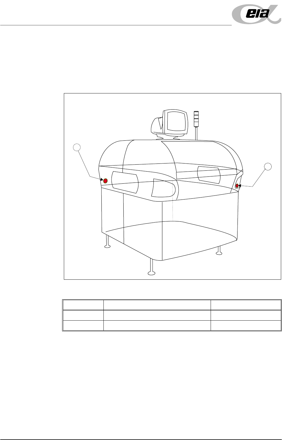
The machine is fitted with two emergency stop push button control switches (one
at the front right corner of the machine and one at the rear left corner of the
machine). Pressing either of these push-buttons (or opening the machine access
covers) cuts the power supply to all motors and selected actuators. A warning
of this condition is reported on the machine monitor.
Figure 2-1 Emergency Stop Push Button Control Switches
Item Description Location
1 Emergency Stop Button (Right Hand Side) Front Cover
2 Emergency Stop Button (Left Hand Side) Rear Cover
2
1