ELA Installation.pdf - 第14页
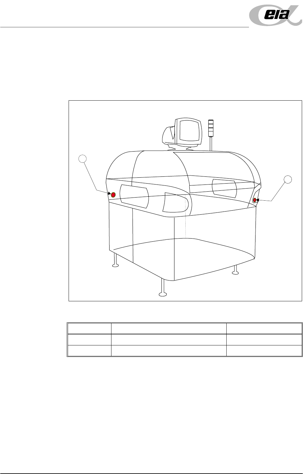
SAFETY FEA TURES EMERGEN CY SHUTDOWN 2.4 I nstallation M anual Chapter Issue 3 Jun 01 EMERGENCY SHUTDO WN The machine is fi tted with two emer gency stop p ush b utton control switches (one at the front right c orner of …

SAFETY FEATURES
PRINTHEAD COVERS
Chapter Issue 3 Jun 01 Installation Manual 2.3
PRINTHEAD COVERS
Access to the machine printhead is achieved by raising the shutter at the front of
the machine.
Access to the stencil and optional under screen cleaner is achieved by lowering
the drop down panel at the front of the machine.
NOTE
The drop down panel can only be lowered if the shutter has been raised. The
drop down panel must also be raised prior to closing the shutter.
The shutter and drop down panel, are fitted with cam safety switches to protect
personnel from the moving mechanisms during normal line operations, opening
either cover cuts power to all motors and selected actuators, via the PNOZ
system safety relay module, to all machine modules.
Perspex side safety covers are fitted to the machine sides to protect personnel
from inadvertent access to the machine around the board entry/exit areas.
Recovery When the covers are closed, normal working condition is restored and the line
may be restarted. Pressing one of the two machine system buttons enables
resumption of operations, where this is allowed by the control system.
SAFETY FEATURES
EMERGENCY SHUTDOWN
2.4 Installation Manual Chapter Issue 3 Jun 01
EMERGENCY SHUTDOWN
The machine is fitted with two emergency stop push button control switches (one
at the front right corner of the machine and one at the rear left corner of the
machine). Pressing either of these push-buttons (or opening the machine access
covers) cuts the power supply to all motors and selected actuators. A warning
of this condition is reported on the machine monitor.
Figure 2-1 Emergency Stop Push Button Control Switches
Item Description Location
1 Emergency Stop Button (Right Hand Side) Front Cover
2 Emergency Stop Button (Left Hand Side) Rear Cover
2
1
SAFETY FEATURES
FRAME COVERS
Chapter Issue 3 Jun 01 Installation Manual 2.5
FRAME COVERS
In order to protect personnel and prevent damage to the machine, six panels are
fitted around the base of the machine. These panels (listed below) may be
removed to assist maintenance.
• Front Panel
• Side Panels - Front (2 positions)
• Side Panels - Rear (2 positions)
• Rear Panel
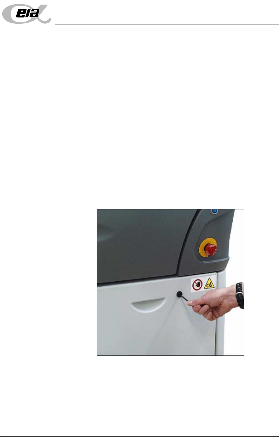
Removal of the front and rear panels requires a maintenance key to release two
locking mechanisms located externally at the top corners of each panel (Panel
Locking Mechanism figure refers ).
The two side front panels on each side of the machine are slid forward of their
internal support lugs at the bottom of the machine, (providing that both the
individual internal quick release fasteners have been released).
The two side rear panels on each side of the machine are slid to the rear of their
internal support lugs at the bottom of the machine, (after the rear panel has been
removed) and their individual internal quick release fasteners (2 positions) have
been released.
Figure 2-2 Panel Locking Mechanism
Enclosures Enclosures are not fitted with a safety interlock. Inadvertent access to such
enclosures is prevented by the presence of the enclosure panels and the frame
covers. However within enclosures, care has been taken to ensure that electri-
cally live components are covered.