ELA Installation.pdf - 第15页
SAFETY FE ATURES FRAME COVE RS Chapter Issu e 3 Jun 01 Installati on Manua l 2.5 FRAME CO VERS In order to protect personnel and prevent damage to the machine, six panels are f itted around the base of the machine. These…
SAFETY FEATURES
EMERGENCY SHUTDOWN
2.4 Installation Manual Chapter Issue 3 Jun 01
EMERGENCY SHUTDOWN
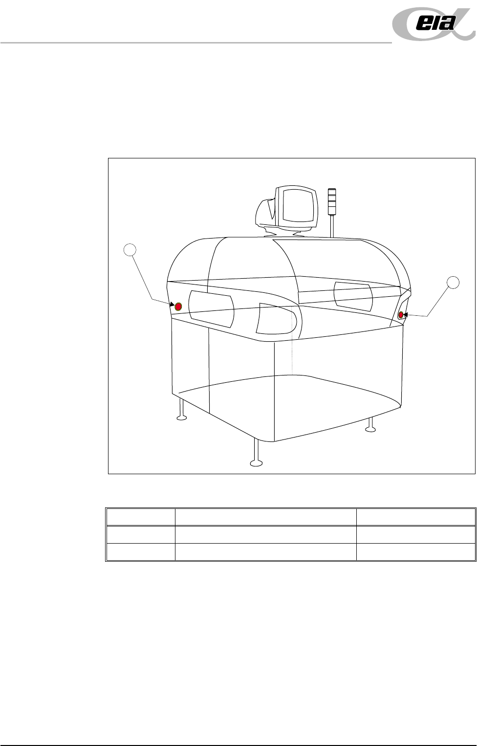
The machine is fitted with two emergency stop push button control switches (one
at the front right corner of the machine and one at the rear left corner of the
machine). Pressing either of these push-buttons (or opening the machine access
covers) cuts the power supply to all motors and selected actuators. A warning
of this condition is reported on the machine monitor.
Figure 2-1 Emergency Stop Push Button Control Switches
Item Description Location
1 Emergency Stop Button (Right Hand Side) Front Cover
2 Emergency Stop Button (Left Hand Side) Rear Cover
2
1
SAFETY FEATURES
FRAME COVERS
Chapter Issue 3 Jun 01 Installation Manual 2.5
FRAME COVERS
In order to protect personnel and prevent damage to the machine, six panels are
fitted around the base of the machine. These panels (listed below) may be
removed to assist maintenance.
• Front Panel
• Side Panels - Front (2 positions)
• Side Panels - Rear (2 positions)
• Rear Panel
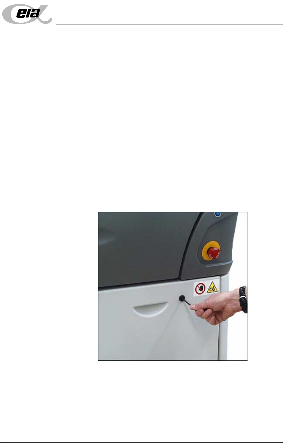
Removal of the front and rear panels requires a maintenance key to release two
locking mechanisms located externally at the top corners of each panel (Panel
Locking Mechanism figure refers ).
The two side front panels on each side of the machine are slid forward of their
internal support lugs at the bottom of the machine, (providing that both the
individual internal quick release fasteners have been released).
The two side rear panels on each side of the machine are slid to the rear of their
internal support lugs at the bottom of the machine, (after the rear panel has been
removed) and their individual internal quick release fasteners (2 positions) have
been released.
Figure 2-2 Panel Locking Mechanism
Enclosures Enclosures are not fitted with a safety interlock. Inadvertent access to such
enclosures is prevented by the presence of the enclosure panels and the frame
covers. However within enclosures, care has been taken to ensure that electri-
cally live components are covered.

SAFETY FEATURES
HIGH VOLTAGE PROTECTION
2.6 Installation Manual Chapter Issue 3 Jun 01
HIGH VOLTAGE PROTECTION
Mechanisms The machine incorporates Class 1 electrical protection according to the IEC 536
requirement 1:1993.
All machines prior to shipment undergo electrical safety tests as described in
EN60204-1 (1997) Section 19:
• 19.2 Continuity of the protective bonding circuit
• 19.3 Insulation resistance test
With the exception of the optional Onboard Suction Filtration Unit, machine
mechanisms are powered by voltages less than 50V and do not pose an electrical
hazard to personnel.
NOTE
Refer to Chapter 5 Machine Preparation (Machine Relocation section) for
information on Vacuum Filtration Unit checks.
Access Where incoming supply voltages are present, protection is afforded by control-
ling access to the enclosures that house the supply. The machine is fitted with a
mains isolator switch that cuts power to all circuits located beyond the switch on
both in coming and out going power terminals. The isolator switch is located at
the front of the machine.
Hazard Warning
Labels
Hazard warning labels are placed on the outside of enclosures where dangerous
voltage (100V-240V) terminations are present within.
Earth Bonding All external metal surfaces are mechanically and electrically bonded to the
machine earth point. The bonding wire used is identified by its green and yellow
insulation and is commonly used to earth bond throughout. Care should be taken
when removing these links that when they are replaced they are secured tightly
and cleanly.