ELA Installation.pdf - 第22页
UNPACK ING INSTR UCT IONS INTRODUCTION 4.2 I nstallation M anual Chapter Issue 3 Jun 01 Miscellan eous Items Ensure the follow ing additional equipment is complete and correct: Documentation Ensure the following m achine…
UNPACKING INSTRUCTIONS
INTRODUCTION
Chapter Issue 3 Jun 01 Installation Manual 4.1
CHAPTER 4 UNPACKING INSTRUCTIONS
INTRODUCTION
General To ensure the machine is not damaged during transportation certain machine
components are removed prior to dispatch, wrapped and packed separately. The
machine mounting feet are removed at dispatch and replaced with transportation
studs, the machine is secured to the base of the transportation box with nuts and
washers. The studs, nuts and washers are replaced on the machine assembly by
the mounting feet.
Unpacking The lids of the transportation boxes are secured with screws. Remove the box
lids and the sides of the large box only. Remove all loose items from the boxes.
Remove the wrapping from around the machine, remove the loose items from
their bags or wrappings.
CAUTION
RED TRANSIT BRACKETS. Do not remove the red transit brackets
attached to the machine until the machine has been moved to its designated
position.
Machine
Components
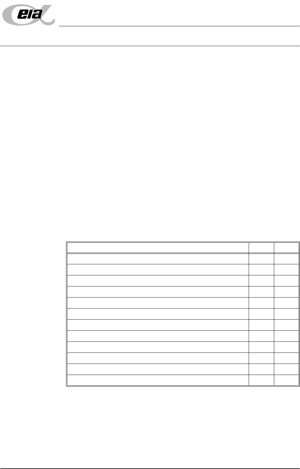
Ensure the following machine components, removed for transportation are
complete and correct:
NOTE
Quantities may vary, depending on customers requirements.
Item Yes No
Machine Mounting Feet
Paste Dispenser Nozzle (if paste dispenser option fitted)
500g Paste Cartridge Sleeve (optional)
Paste Dispenser Drip Tray (if paste dispenser option fitted)
Squeegee Paste Drip Tray
Squeegees (if applicable)
ProFlow Unit (optional)
Monitor
IR Keyboard/Mouse Unit / IR Receiver Unit
Tricolour Beacon
Magnetic Tool Pins
Manifold (if TCU fitted)
UNPACKING INSTRUCTIONS
INTRODUCTION
4.2 Installation Manual Chapter Issue 3 Jun 01
Miscellaneous
Items
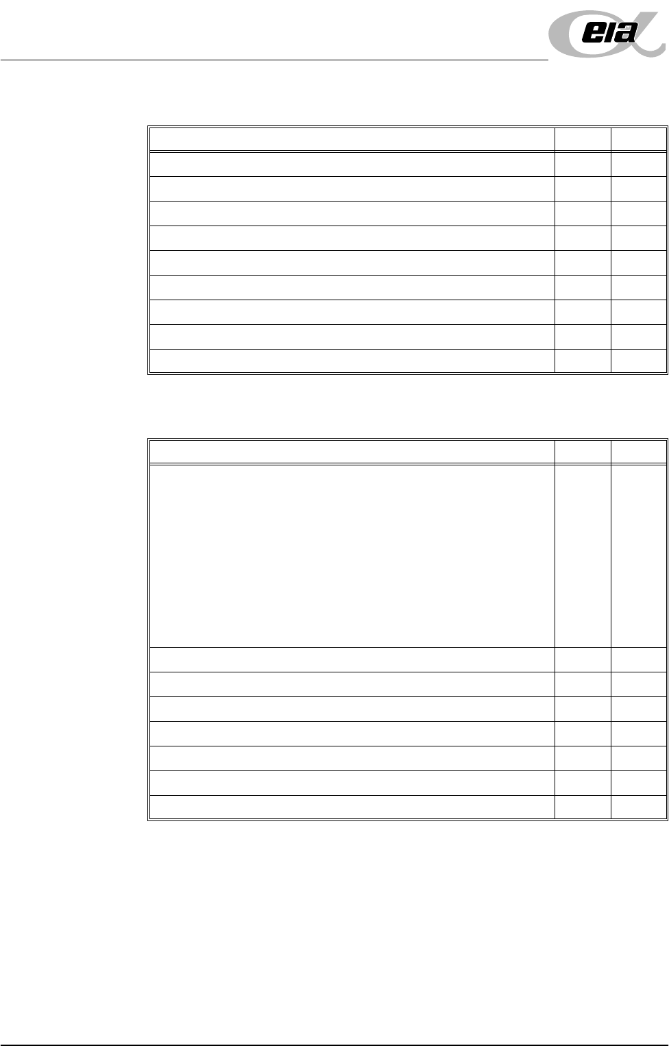
Ensure the following additional equipment is complete and correct:
Documentation Ensure the following machine documentation is complete and correct:
Item Yes No
Calibration Screen
Calibration Board
Alignment Test Board
Board Clamp Setting Plate
FMI Leads (if applicable)
Paste Deflectors, set of 2 (4 items total)
Rail to Table Height Setting Plates (2 items)
Spares Kit (if ordered)
DEK ELA Software / DEK ELA Recovery CD-ROM
Item Yes No
ELA Technical Manuals CD-ROM incorporating:
• Operator Manuals (in all available languages)
• Technical Reference Manual
• User Manual
• Installation Manual
• Electrical Drawings
• Mechanical Drawings
Installation Manual (paper)
Operator Manual (Paper)
Solvent Data Sheet (optional)
Configuration & Dispatch Procedures
Alignment Data
CE Certificate
DEK Delivery Questionnaire

UNPACKING INSTRUCTIONS
INTRODUCTION
Chapter Issue 3 Jun 01 Installation Manual 4.3
Inventory Using the Sales Acknowledgment sheet check the machine against the customer
machine configuration - Machine Components, Miscellaneous Items and Docu-
mentation as listed.
If any components or items are missing or faulty, make a note of this on the
Outstanding Issues page found in Chapter 9 - Installation Documentation of this
manual.
Inspection Visually inspect all machine components and equipment for completeness,
condition and damage.
If any components or equipment are incomplete, damaged or in poor condition,
make a note of this on the Outstanding Issues page found in Chapter 9 -
Installation Documentation of this manual.