ELA Installation.pdf - 第23页
UNPACKING INSTRUCTIONS INTRODUCTION Chapter Issu e 3 Jun 01 Installati on Manua l 4.3 In ventory Using the Sa les Acknowledgment sheet check t he machi ne against the c ustomer machine configuration - Machine Components,…
UNPACKING INSTRUCTIONS
INTRODUCTION
4.2 Installation Manual Chapter Issue 3 Jun 01
Miscellaneous
Items
Ensure the following additional equipment is complete and correct:
Documentation Ensure the following machine documentation is complete and correct:
Item Yes No
Calibration Screen
Calibration Board
Alignment Test Board
Board Clamp Setting Plate
FMI Leads (if applicable)
Paste Deflectors, set of 2 (4 items total)
Rail to Table Height Setting Plates (2 items)
Spares Kit (if ordered)
DEK ELA Software / DEK ELA Recovery CD-ROM
Item Yes No
ELA Technical Manuals CD-ROM incorporating:
• Operator Manuals (in all available languages)
• Technical Reference Manual
• User Manual
• Installation Manual
• Electrical Drawings
• Mechanical Drawings
Installation Manual (paper)
Operator Manual (Paper)
Solvent Data Sheet (optional)
Configuration & Dispatch Procedures
Alignment Data
CE Certificate
DEK Delivery Questionnaire

UNPACKING INSTRUCTIONS
INTRODUCTION
Chapter Issue 3 Jun 01 Installation Manual 4.3
Inventory Using the Sales Acknowledgment sheet check the machine against the customer
machine configuration - Machine Components, Miscellaneous Items and Docu-
mentation as listed.
If any components or items are missing or faulty, make a note of this on the
Outstanding Issues page found in Chapter 9 - Installation Documentation of this
manual.
Inspection Visually inspect all machine components and equipment for completeness,
condition and damage.
If any components or equipment are incomplete, damaged or in poor condition,
make a note of this on the Outstanding Issues page found in Chapter 9 -
Installation Documentation of this manual.
UNPACKING INSTRUCTIONS
TRANSPORTATION
4.4 Installation Manual Chapter Issue 3 Jun 01
TRANSPORTATION
WARNING
MACHINE LIFTING. TO PREVENT SERIOUS INJURY TO
PERSONNEL, DURING LIFTING AND TRANSPORTATION
OPERATIONS, ENSURE THE MACHINE IS LIFTED AND
TRANSPORTED IN ACCORDANCE WITH INSTRUCTIONS
DETAILED IN THIS SECTION.
CAUTION
MACHINE DAMAGE. Damage to the machine may occur if the machine
is lifted incorrectly.
1. Do not raise the machine using lifting strops.
2. Do not lift the machine from the sides.
Remove the four nuts and washers securing the machine to the transportation
box base using a 36mm spanner (wrench).
The machine may be lifted using a fork-lift truck or similar machine that meets
the following criteria:
• Minimum fork length of 54" (1372mm)
• 27"min (686mm) / 54"max (914mm) fork span
• Lifting capability of 2000kg
1. Locate the forks under the machine base (preferably from the rear) so the
weight of the machine is taken evenly on the front and rear cross members
(Machine on Fork-lift figure refers).
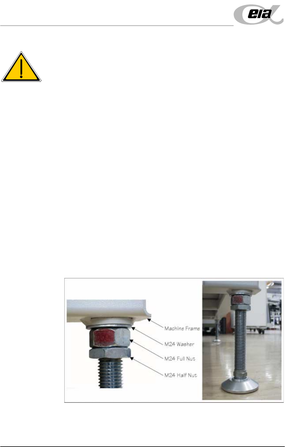
2. Fit the four mounting feet, as detailed in the figure below. Adjust the height
of each foot to approximately the same height, secure in place by tightening
the nuts.
Figure 4-1 Mounting Feet Arrangement