ELA Installation.pdf - 第31页
MACHI NE PRE PARAT ION REMOVAL PROC EDURES Chapter Issu e 3 Jun 01 Installati on Manua l 5.5 Rear T ransit Bracket Figur e 5-3 Rear T ransit Bracket 1. Loosen the M8 nuts (Item 3) abov e and belo w the left and right han…
MACHINE PREPARATION
REMOVAL PROCEDURES
5.4 Installation Manual Chapter Issue 3 Jun 01
REMOVAL PROCEDURES
To remove the transit brackets from the machine, refer to the following proce-
dures:
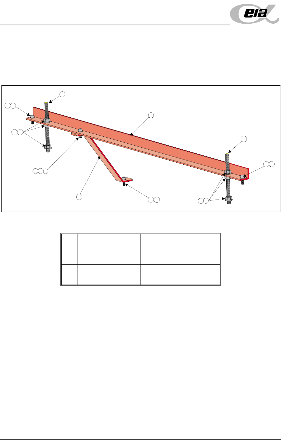
Front Transit Bracket
Figure 5-2 Front Transit Bracket (With Camera Bracket Fitted)
1. Remove the M5 cap head screw (Item 3) and washer (Item 8) securing the
camera transit bracket (Item 6) to the camera carriage. Loosen the M5 cap
head screw and nut at the top of the camera transit bracket and rotate the
bracket clear of the camera X axis timing belt.
2. On each of the M8 studs (Item 2), loosen the nuts and washers (Items 5 and
4) either side of the transit bracket, loosen the M8 nuts (Item 5) securing the
M8 studs (Item 2) to the screen chase. Unscrew the studs (Item 2) from the
screen chase.
3. Unscrew the two M5 cap head screws (Item 3) securing the front transit
bracket to the printhead.
4. Remove the front transit bracket.
Item Description Item Description
1 Front Transit Bracket 5 M8 Nut
2 M8 Stud 6 Camera Transit Bracket
3 M5 Cap Head Screw 7 M5 Ni-Loc Nut
4M8 Washer 8M5 Washer
3
1
6
2
2
8
8
3
7
8
3
3
8
4
5
4
5
MACHINE PREPARATION
REMOVAL PROCEDURES
Chapter Issue 3 Jun 01 Installation Manual 5.5
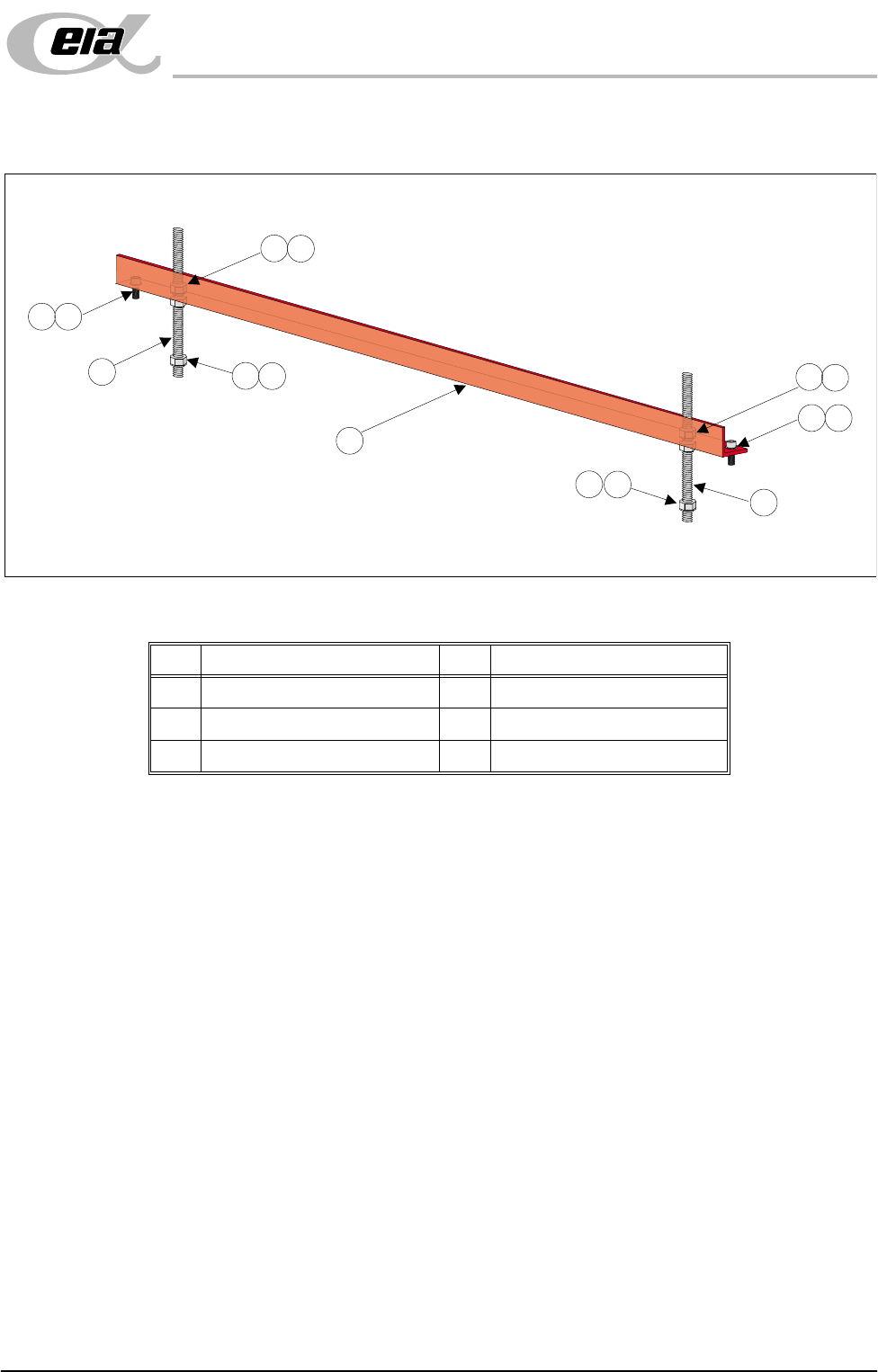
Rear Transit Bracket
Figure 5-3 Rear Transit Bracket
1. Loosen the M8 nuts (Item 3) above and below the left and right hand sides
of the bracket (Item 6).
2. Unscrew the left hand and right hand M8 studs (Item 5) from the screen
chase.
3. Remove the two M5 cap head screws (Item 1) securing the left hand and right
hand sides of the bracket (Item 6) to the printhead casting.
4. Carefully remove the rear transit bracket.
Item Description Item Description
1 M5 Cap Head Screw 4 M8 Washer
2M5 Washer 5M8 Stud
3 M8 Nut 6 Rear Transit Bracket
1
2
1
2
3
3
4
3
4
3
4
4
5
5
6
MACHINE PREPARATION
REMOVAL PROCEDURES
5.6 Installation Manual Chapter Issue 3 Jun 01
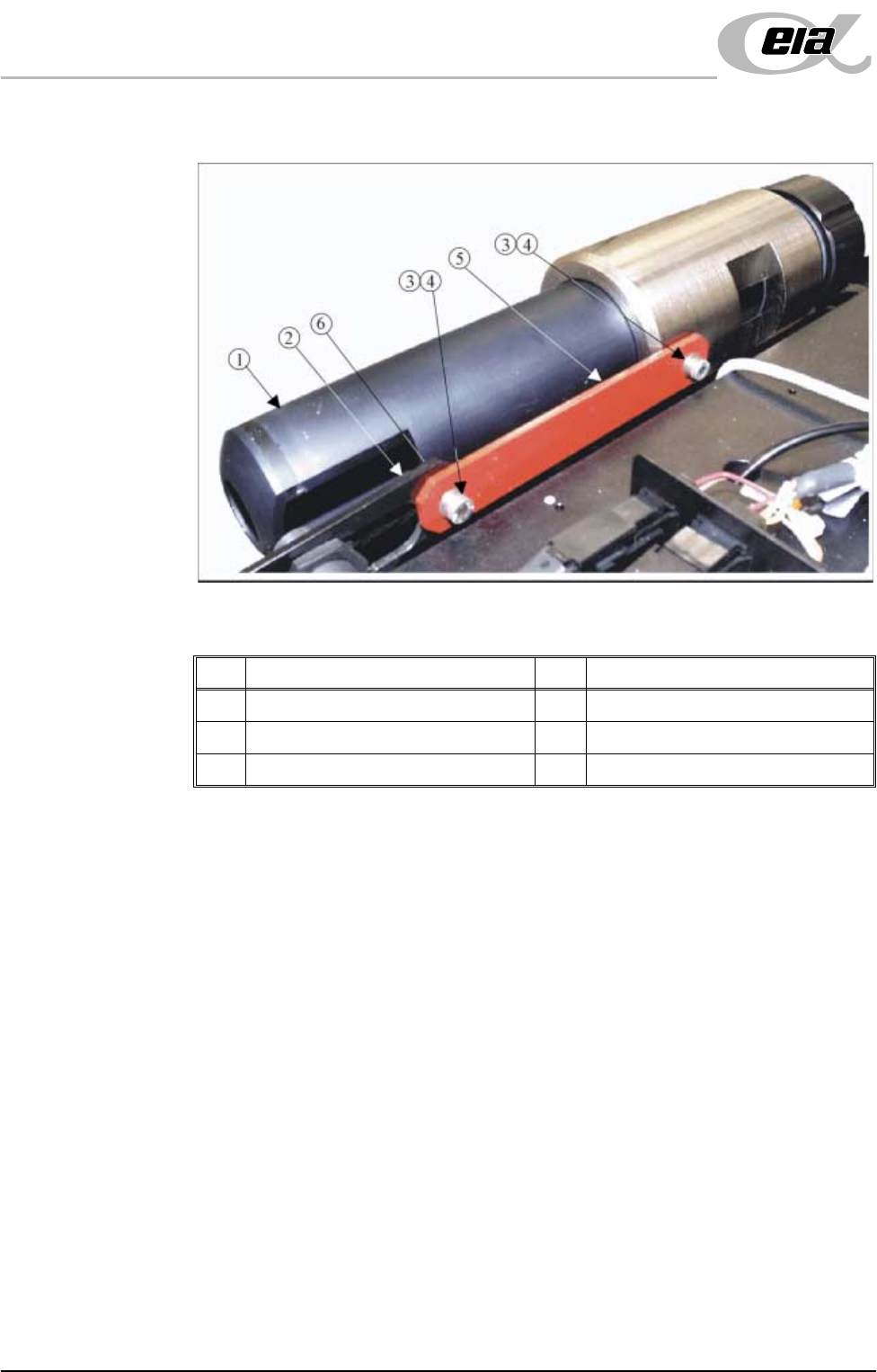
Paste Dispense Transit Bracket
Figure 5-4 Paste Dispenser Transit Bracket
1. Remove the M5 cap head screw, M5 washer (Items 4, 3 and 6) and M5 nut
securing the left hand side of the transit bracket (Item 5) to the paste low
sensor mounting bracket (Item 2).
2. Remove the remaining M5 cap head screw and M5 washer (Items 4 and 3)
securing the right hand side of the transit bracket (Item 5) to the paste
dispenser and remove the transit bracket.
Item Description Item Description
1 Paste Dispenser 4 M5 Cap Head Screw
2 Paste Low Sensor Mounting Brackets 5 Paste Dispenser Transit Bracket
3 M5 Washer 6 M5 Nut (concealed from view)