ELA Installation.pdf - 第32页
MACHI NE PRE PARAT ION REMOVAL PR OCEDURES 5.6 I nstallation M anual Chapter Issue 3 Jun 01 Paste Dispense T r ansit Bracket Figur e 5-4 Paste Dispenser T ransit Bracket 1. Remov e the M5 cap he ad screw , M5 washer (Ite…
MACHINE PREPARATION
REMOVAL PROCEDURES
Chapter Issue 3 Jun 01 Installation Manual 5.5
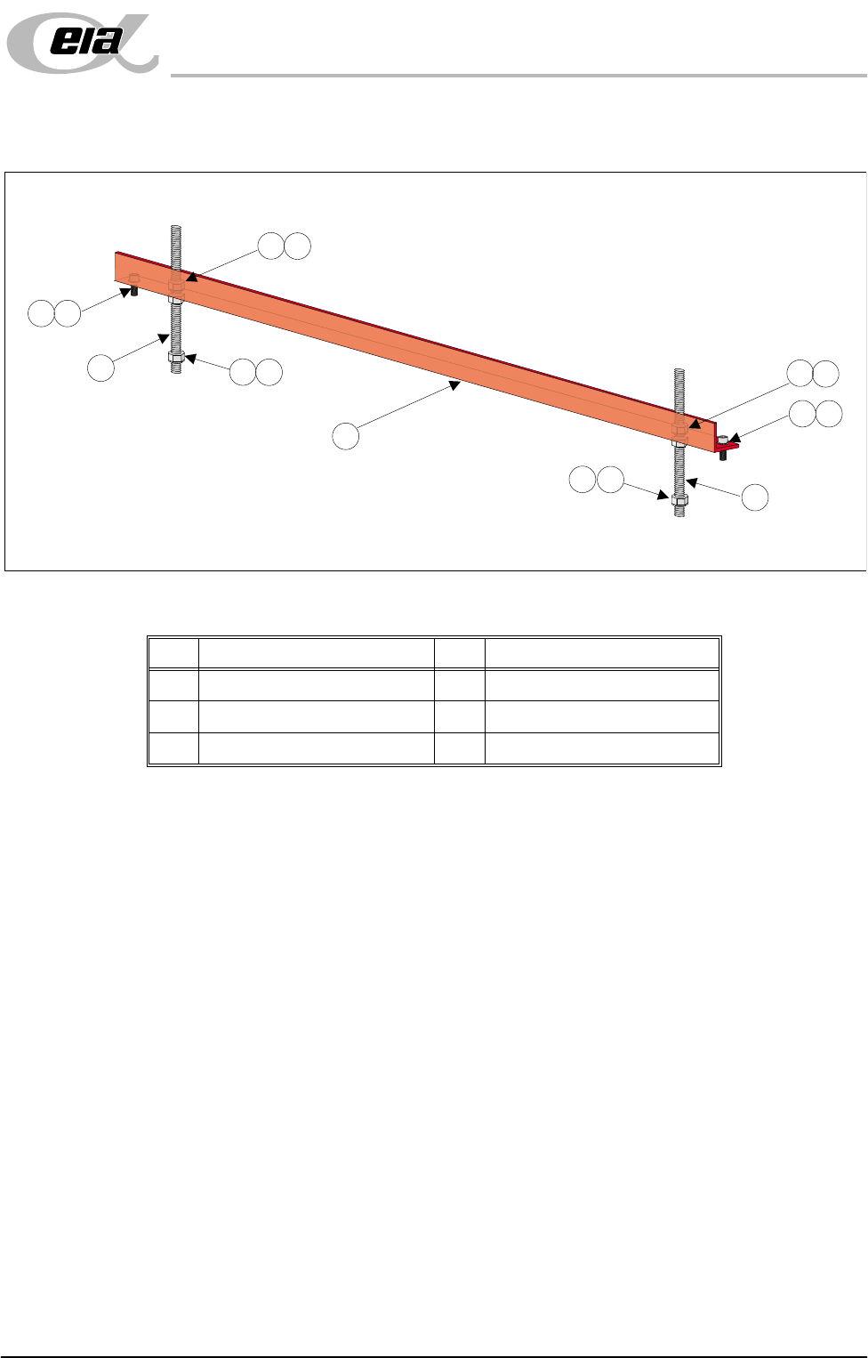
Rear Transit Bracket
Figure 5-3 Rear Transit Bracket
1. Loosen the M8 nuts (Item 3) above and below the left and right hand sides
of the bracket (Item 6).
2. Unscrew the left hand and right hand M8 studs (Item 5) from the screen
chase.
3. Remove the two M5 cap head screws (Item 1) securing the left hand and right
hand sides of the bracket (Item 6) to the printhead casting.
4. Carefully remove the rear transit bracket.
Item Description Item Description
1 M5 Cap Head Screw 4 M8 Washer
2M5 Washer 5M8 Stud
3 M8 Nut 6 Rear Transit Bracket
1
2
1
2
3
3
4
3
4
3
4
4
5
5
6
MACHINE PREPARATION
REMOVAL PROCEDURES
5.6 Installation Manual Chapter Issue 3 Jun 01
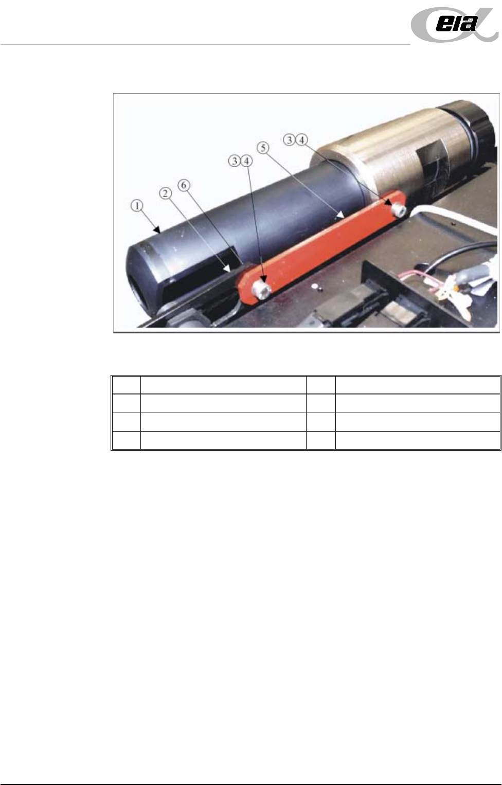
Paste Dispense Transit Bracket
Figure 5-4 Paste Dispenser Transit Bracket
1. Remove the M5 cap head screw, M5 washer (Items 4, 3 and 6) and M5 nut
securing the left hand side of the transit bracket (Item 5) to the paste low
sensor mounting bracket (Item 2).
2. Remove the remaining M5 cap head screw and M5 washer (Items 4 and 3)
securing the right hand side of the transit bracket (Item 5) to the paste
dispenser and remove the transit bracket.
Item Description Item Description
1 Paste Dispenser 4 M5 Cap Head Screw
2 Paste Low Sensor Mounting Brackets 5 Paste Dispenser Transit Bracket
3 M5 Washer 6 M5 Nut (concealed from view)
MACHINE PREPARATION
REMOVAL PROCEDURES
Chapter Issue 3 Jun 01 Installation Manual 5.7
Actuator Restrainer Brackets
CAUTION
INSTALLING/REMOVING SCREEN ACTUATOR BRACKETS.
Extreme care must be taken when installing or removing the screen actua-
tor clamps as the chase is spring loaded against the screen actuator ends in
the X Forward, X Rear and Y Axis Positions. Impact force may damage the
actuators.
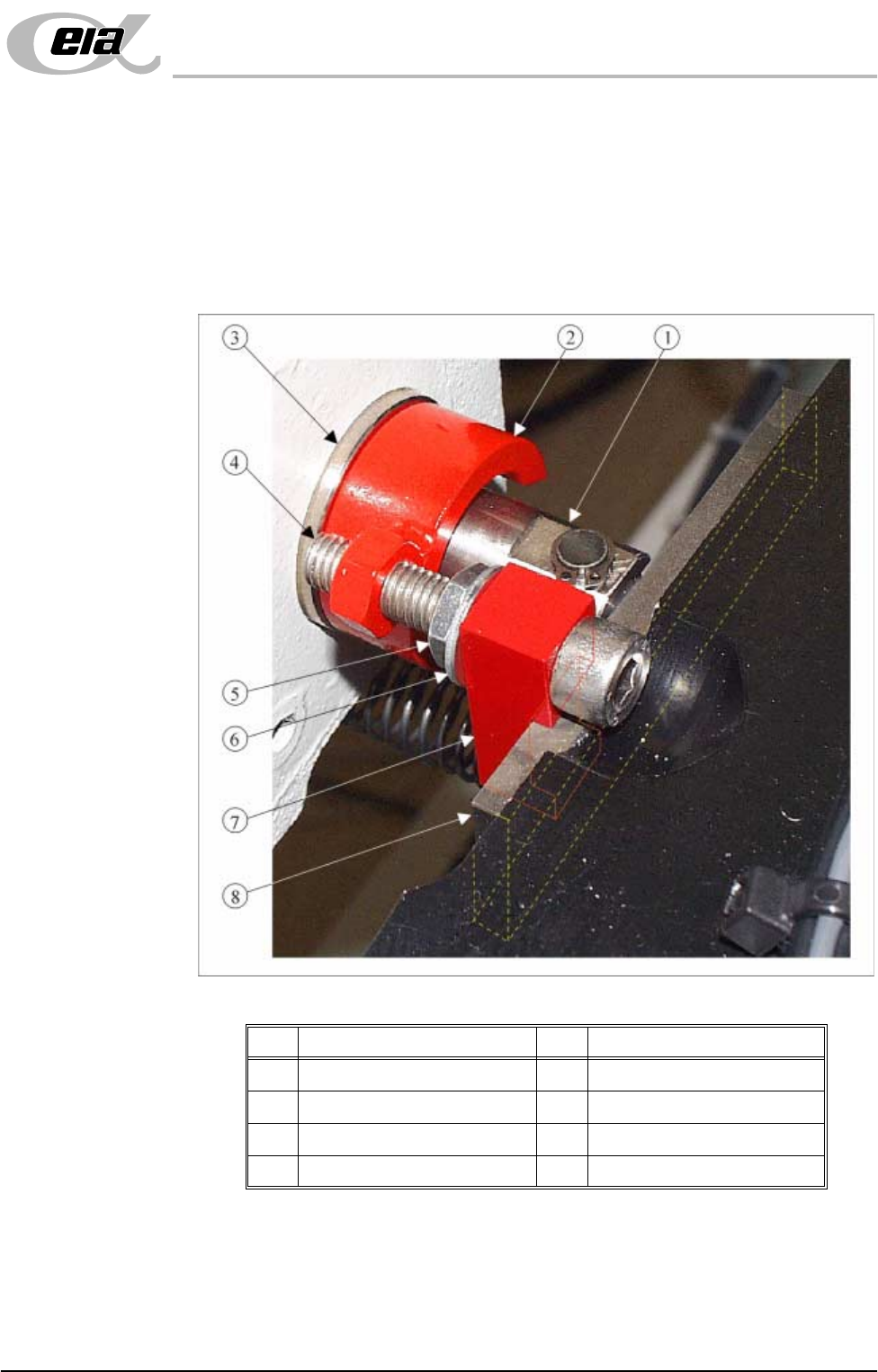
Figure 5-5 Chase Restrainer Clamp
1. Slowly loosen the M8 nuts and bolts (Items 5 and 4) of the X forward, X rear
and Y axis chase restrainer clamps until each actuator is in full contact with
its relevant chase striker plate (Item 8).
2. On each of the three clamps, continue to unscrew the M8 nut (Item 5) until
sufficient play exists in the clamp to allow the block (Item 7) surrounding the
chase striker plate (Item 8) to be withdrawn and the clamp removed.
Item Description Item Description
1 Actuator Shaft 5 M8 Nut
2 Restrainer Collar 6 M8 Washer
3 Actuator 7 Block
4 M8 Bolt 8 Striker Plate