ELA Installation.pdf - 第40页
MACHI NE PRE PARAT ION MACHI NE A SSEMB LY 5.14 Installati on Manua l Chapter Iss ue 3 Jun 01 2. Fit the pressure me chanism part of the ProFl o w unit to the ProFlo w printhead mechanism bearing block by means of the tw…
MACHINE PREPARATION
MACHINE ASSEMBLY
Chapter Issue 3 Jun 01 Installation Manual 5.13
MACHINE ASSEMBLY
Assemble the machine components and assemblies removed for transportation
to the machine, as listed in the Machine Components table in Chapter 4.
Monitor and IR
Receiver
1. Position the monitor centrally on the top of the machine.
2. Connect the monitor as follows:
a. Connect 14SK10 (power) from the cover connector plate to the monitor.
b. Connect 14PL31 from the monitor to 14SK31 on the cover connector
plate.
c. Connect the infra red receiver unit leads 14PL32 (keyboard) and 14PL33
(mouse) to 14SK32 and 14SK33 respectively on the cover connector plate.
Tricolour Beacon 1. Assemble the tricolour beacon assembly to the bracket on the right hand side
of the machine.
2. Connect the tricolour beacon 14PL07 to 14SK07 at the beacon bracket.
ProFlow For ProFlow only machines:
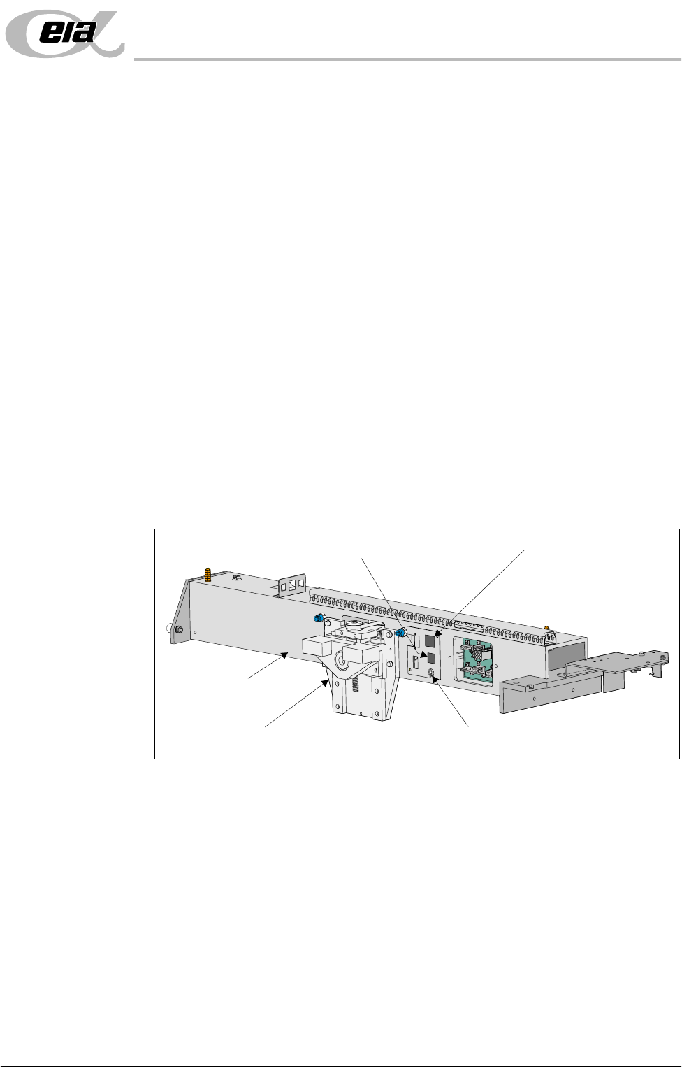
1. Fit the following ProFlow mechanism connectors (figure below refers):
• ProFlow motor connector 9PL17 into 9 way socket 9SK17
• ProFlow home sensor connector 9PL08 into 6 way socket 9SK08
Print Carriage
ProFlow (Printhead) Mechanism
9SK08 (Home Sensor)
ProFlow Fitted Socket
9SK17 (ProFlow Motor)
MACHINE PREPARATION
MACHINE ASSEMBLY
5.14 Installation Manual Chapter Issue 3 Jun 01
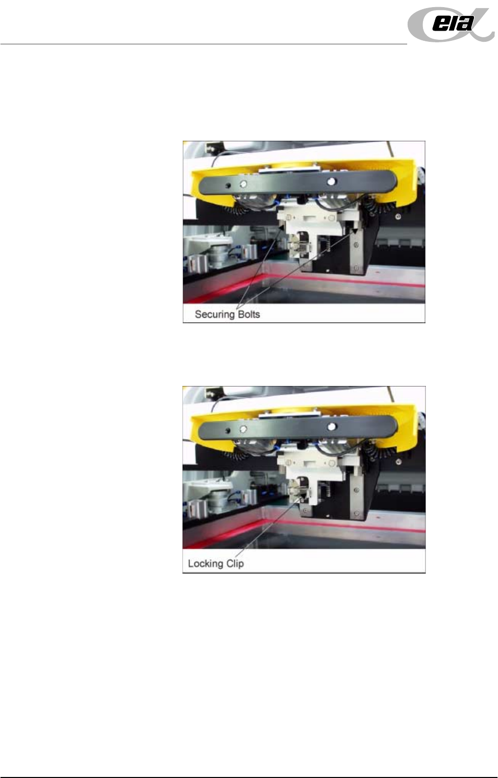
2. Fit the pressure mechanism part of the ProFlow unit to the ProFlow printhead
mechanism bearing block by means of the two securing bolts. Tighten using
a 5mm Allen key.
NOTE
Unit shown in unlatched position to identify bolts..
3. Ensure that the locking clip on the pressure mechanism is pressed over to the
right and clicks into place, as shown in the figure below. This ensures that
the locking clip is in the correct position to secure the transfer head.
MACHINE PREPARATION
MACHINE ASSEMBLY
Chapter Issue 3 Jun 01 Installation Manual 5.15
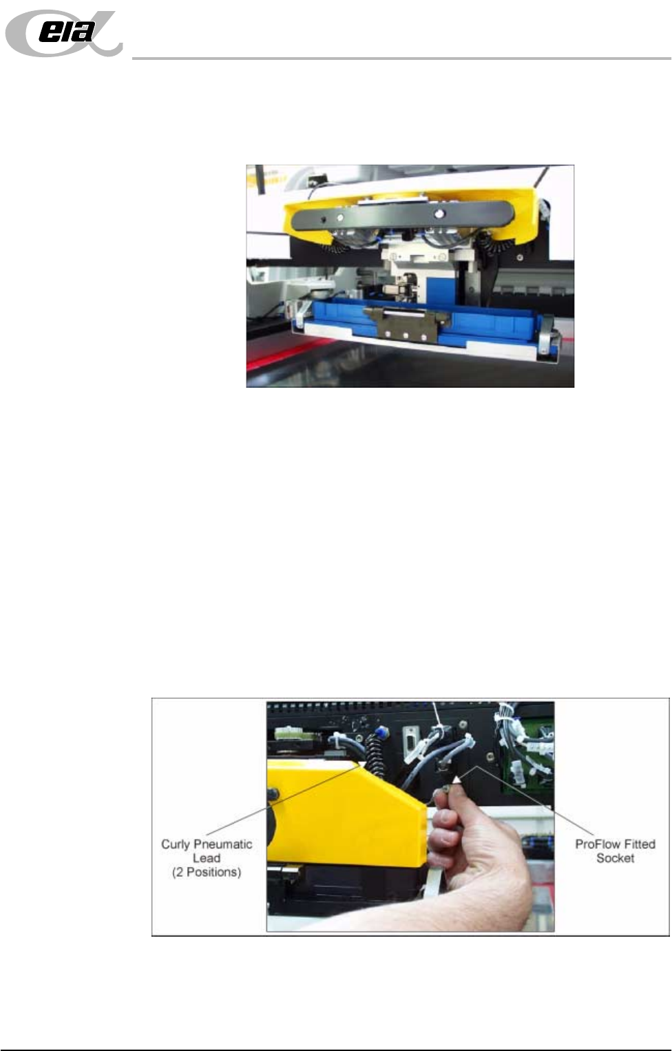
4. Locate and fit the ProFlow transfer head unit to the pressure mechanism by
means of the two locating dowels. Slide the unit onto the pressure mecha-
nism. Once the unit is slid fully home, it is secured by closing the locking
clip.
5. Plug the electrical connection ProFlow Fitted from the ProFlow unit into the
socket sited on the right hand side of the ProFlow on the print carriage,
(Figure below refers).
CAUTION
ELECTRICAL CONNECTION. This electrical connection informs the
machine of ProFlow fitment and must always be connected whilst the
ProFlow unit is fitted otherwise damage may occur if machine is run.
Connect the curly pneumatic leads from the pressure mechanism to each
respective left and right pneumatic connector sited either side of the ProFlow
printhead mechanism.
NOTE
If the squeegee paste dispenser option is fitted to the print carriage, before
using ProFlow, ensure that the paste dispenser regulator gauge reads '0'
pressure.