ELA Installation.pdf - 第41页
MACHI NE PRE PARAT ION MACHI NE ASSE MBLY Chapter Issu e 3 Jun 01 Installati on Manua l 5.15 4. Locate and fit the ProFlo w transfer head unit to the pressure mec hanism by means of the tw o locating do wels. Slide the u…
MACHINE PREPARATION
MACHINE ASSEMBLY
5.14 Installation Manual Chapter Issue 3 Jun 01
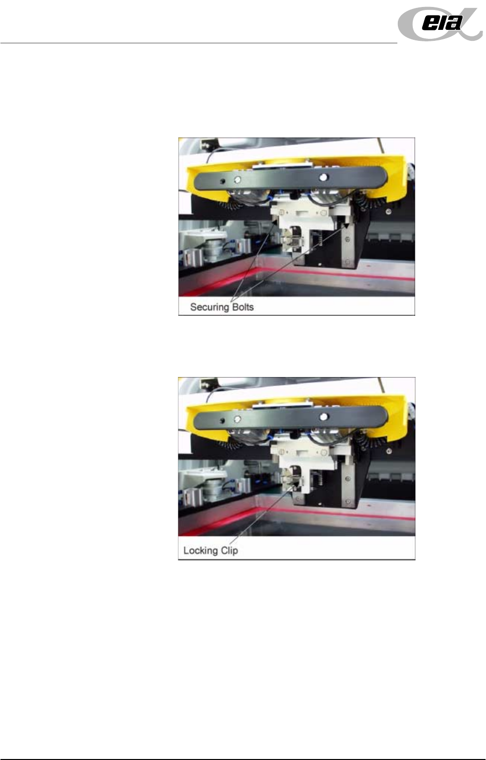
2. Fit the pressure mechanism part of the ProFlow unit to the ProFlow printhead
mechanism bearing block by means of the two securing bolts. Tighten using
a 5mm Allen key.
NOTE
Unit shown in unlatched position to identify bolts..
3. Ensure that the locking clip on the pressure mechanism is pressed over to the
right and clicks into place, as shown in the figure below. This ensures that
the locking clip is in the correct position to secure the transfer head.
MACHINE PREPARATION
MACHINE ASSEMBLY
Chapter Issue 3 Jun 01 Installation Manual 5.15
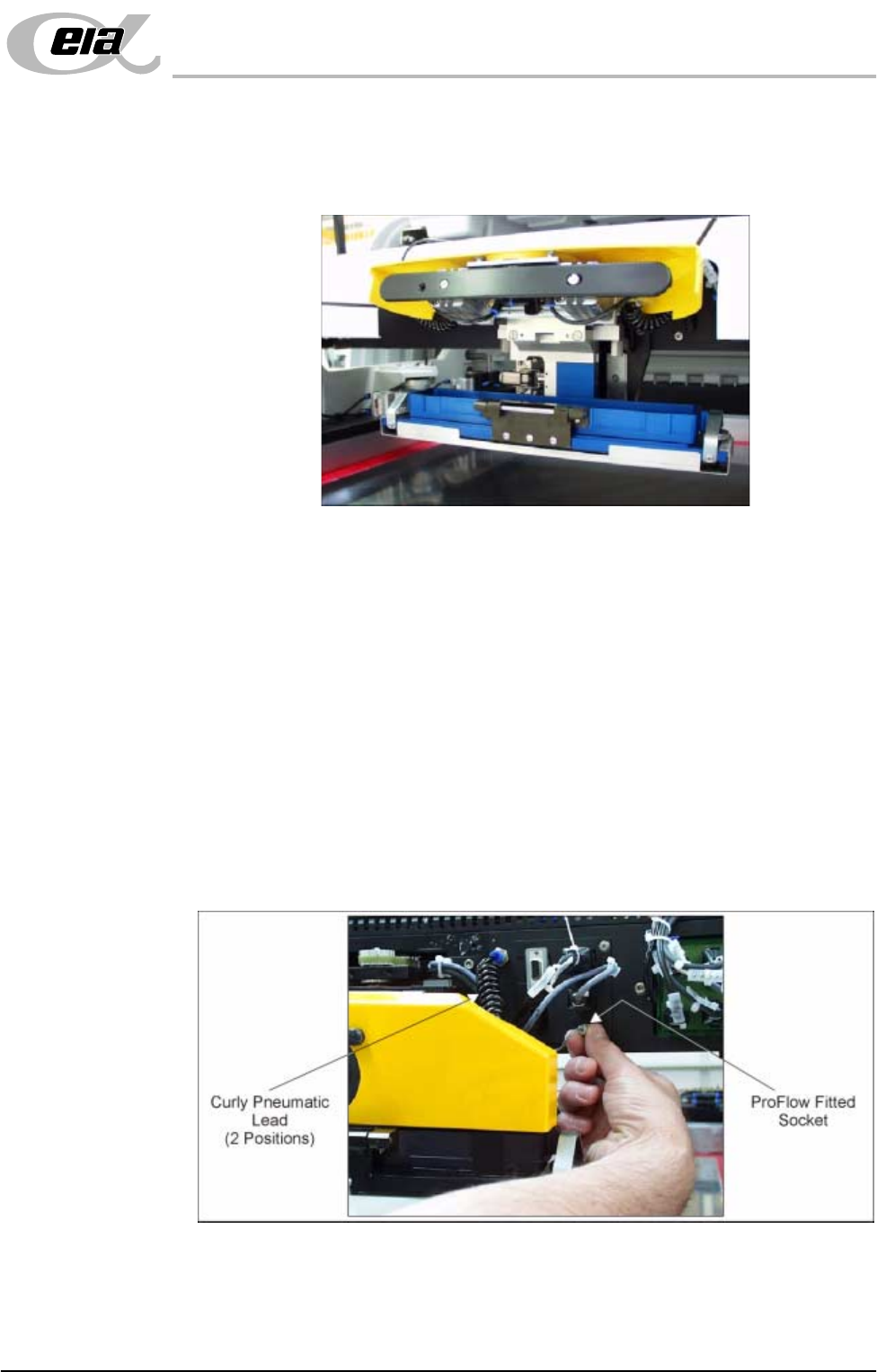
4. Locate and fit the ProFlow transfer head unit to the pressure mechanism by
means of the two locating dowels. Slide the unit onto the pressure mecha-
nism. Once the unit is slid fully home, it is secured by closing the locking
clip.
5. Plug the electrical connection ProFlow Fitted from the ProFlow unit into the
socket sited on the right hand side of the ProFlow on the print carriage,
(Figure below refers).
CAUTION
ELECTRICAL CONNECTION. This electrical connection informs the
machine of ProFlow fitment and must always be connected whilst the
ProFlow unit is fitted otherwise damage may occur if machine is run.
Connect the curly pneumatic leads from the pressure mechanism to each
respective left and right pneumatic connector sited either side of the ProFlow
printhead mechanism.
NOTE
If the squeegee paste dispenser option is fitted to the print carriage, before
using ProFlow, ensure that the paste dispenser regulator gauge reads '0'
pressure.

MACHINE PREPARATION
PRE-INSTALLATION CHECKS
5.16 Installation Manual Chapter Issue 3 Jun 01
PRE-INSTALLATION CHECKS
Having removed the transit brackets and located the machine in position, prepare
to install the machine, as follows:
1. Ensure machine mains isolator is OFF.
2. Connect the pneumatic supply to the connection on the external services
panel, as detailed in Chapter 3.
NOTE
Do not connect the electrical supply to the machine until the electrical
services have been verified, as stated in Chapter 6 - Electrical Services.
3. Check that the E Stop loop is connected, either to the external machines, in
which case these machines must be powered up and operational in order for
the loop to be closed, or if the external E Stop loop is not required then the
dummy plugs supplied with the machine must be connected.
4. Check that all circuit breakers are in the ON position.
5. Ensure that all access covers and removable panels are closed and are in
place, Chapter 2 - Safety Features refers.
6. Ensure that the E Stop buttons are in the fully out position. To check this,
push the E Stop button until it latches. Twist the button clockwise to release
it.
7. Check that all the cables for the monitor and IR receiver unit are connected.
8. Check the IR keyboard/mouse bit switch settings are correct, in accordance
with the config and despatch record.
NOTE
Carry out the following IR Bit Switch Settings procedure if required.
IR Keyboard/
Mouse Frequency
Setting
NOTE
The combination setting for each machine is factory set and logged onto the
machine Configuration and Despatch documentation. This combination is also
recorded onto a DEK database for each machine serial number. DEK must be
informed of any change to the set combination.
The infra red keyboard and mouse has a combination of 16 settings which can
be changed for the following reasons:
• Adjacent machine frequency conflict.
• Keyboard/Mouse unit replacement.
Carry out the following procedure to change the frequency combination setting:
1. Turn the hand held infra red keyboard/mouse upside down.
2. Unclip and remove the battery compartment panel. A four way bit switch is
located in the top left hand corner of the battery compartment, (figure
overleaf refers).