ELA Installation.pdf - 第44页
MACHI NE PRE PARAT ION MACHINE LEVELLIN G 5.18 Installati on Manua l Chapter Iss ue 3 Jun 01 MA CHINE LEVELLING General Before operation, the machine must be installed at the corr ect height and le v el. Machin e Height …
MACHINE PREPARATION
PRE-INSTALLATION CHECKS
Chapter Issue 3 Jun 01 Installation Manual 5.17
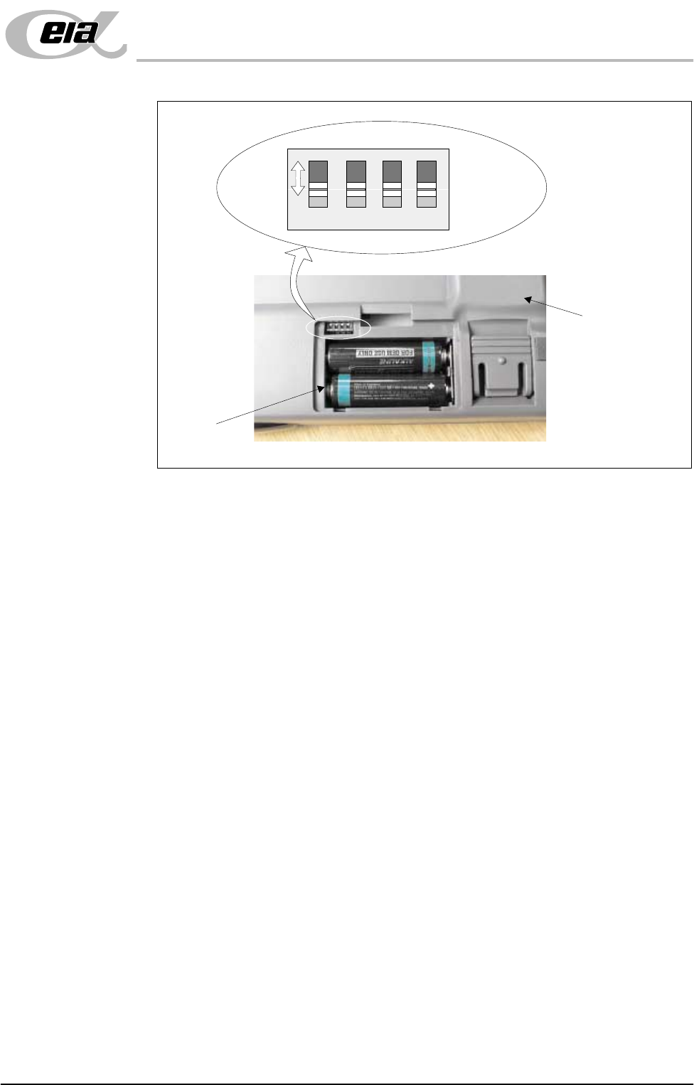
3. Using a suitable tool (eg instrument screwdriver) move the four bit switches
to any of the 16 configurations (each switch has two positions, the figure
above shows all four switches in the forward position).
4. When a switch setting is made the infra red receiver unit has to be set to
recognise the new keyboard configuration.
5. Point the configured keyboard (infra red transmitter window) at the IR
receiver unit on top of the monitor. At the same time locate and press the
ID_ACK button on the underside of the IR receiver unit using the instrument
screwdriver. The receiver interrogates the keyboard and dedicates the fre-
quency configuration to that machine.
The keyboard/mouse is now ready for use.
NOTE
Step 5 above is also carried out whenever the infra red keyboard/mouse batteries
are replaced.
Underside of IR
Keyboard/Mouse
Battery
Compartment
1 2 3 4
ON
Bit Switches
MACHINE PREPARATION
MACHINE LEVELLING
5.18 Installation Manual Chapter Issue 3 Jun 01
MACHINE LEVELLING
General Before operation, the machine must be installed at the correct height and level.
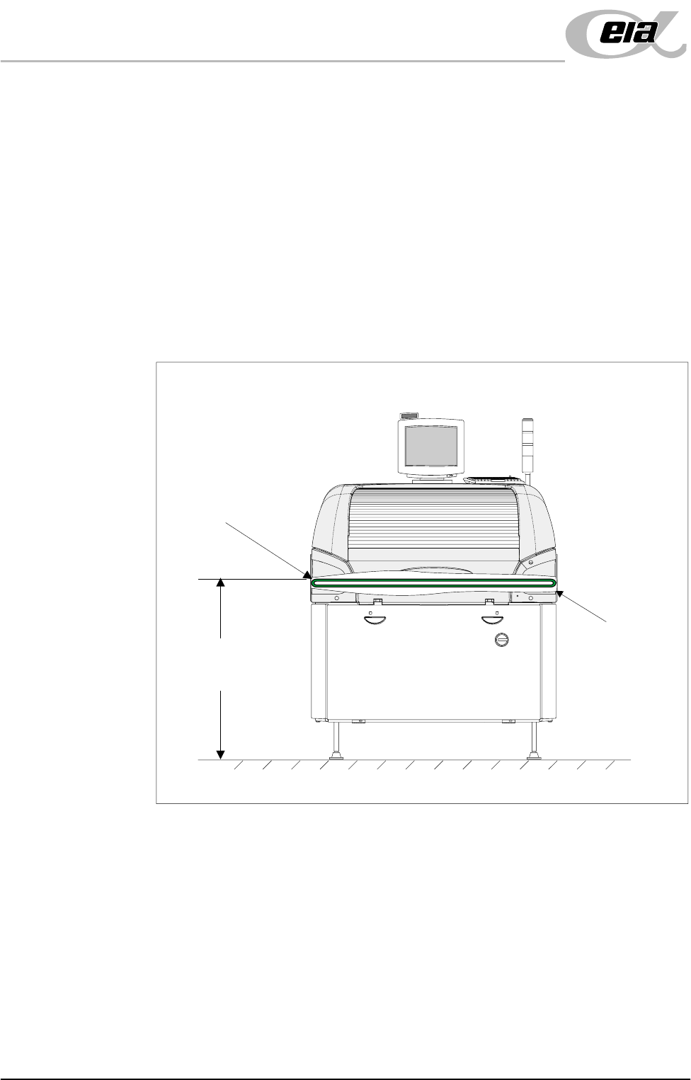
Machine Height The height of the machine is governed by the external machines it is to be
connected to and ranges from 840mm to 980mm (depending if the feet exten-
sions are fitted). The height is measured from the floor to the top of the transport
belts, Machine Height figure below refers.
NOTE
To achieve reliable DEK SPC testing and Cp/Cpk results, the securing arrange-
ment of the four machine legs must be correct in accordance with the Mounting
Feet Arrangement diagram, (Major Relocation chapter - Unpacking section).
This arrangement increases the rigidity of securing the feet to the frame.
Figure 5-10 Machine Height
Height to Top of
Transport Belts
840mm to 980mm
View on Front of Machine
Transport Belts
Cutaway to
Show Belt
MACHINE PREPARATION
MACHINE LEVELLING
Chapter Issue 3 Jun 01 Installation Manual 5.19
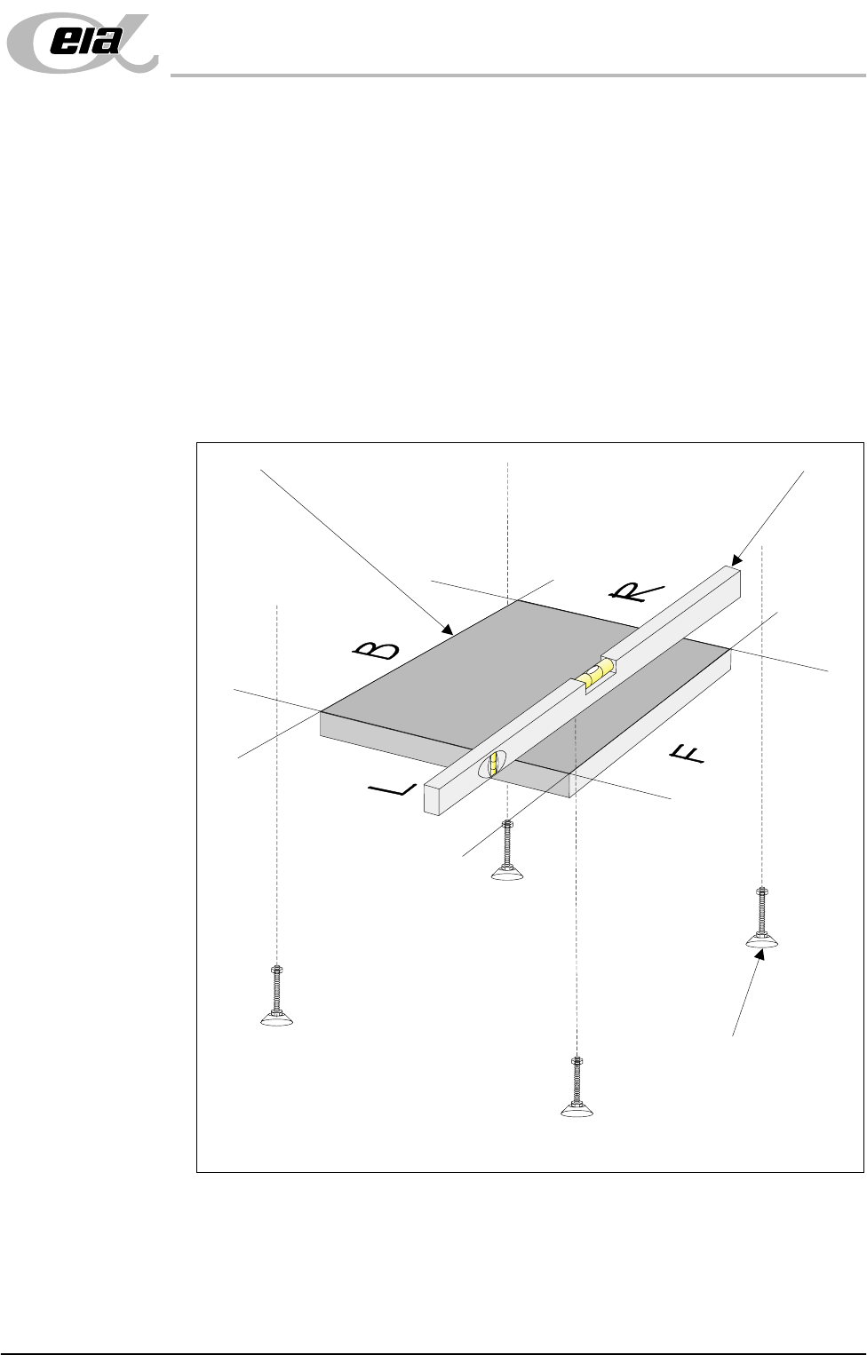
Initial Levelling When the correct height of the machine has been achieved, the four feet should
now be adjusted for correct level.
1. Place an engineering level on the tooling base plate facing Left (L) - Right
(R) or Back (B) - Front (F).
2. By carefully adjusting each of the four feet individually, level the machine
so that in each direction, Left (L) - Right (R) and Back (B) - Front (F), 0.004"
per foot (0.32mm/metre) is achieved.
3. Lock the feet using the locknuts on the adjusters.
Check that the machine height has not been disturbed. If machine height
requires further adjustment, carry out Machine Height and Machine Levelling
until the correct machine height and level is achieved.
Figure 5-11 Machine Levelling
Isometric View Showing Levelling of Tooling Base Plate
Tooling Base Plate
Engineering Level
Adjustable Mounting Feet
(4 positions)