ELA Installation.pdf - 第46页
MACHI NE PRE PARAT ION SHOCK WATCHE S 5.20 Installati on Manua l Chapter Iss ue 3 Jun 01 SHOCK W A TCHES A self adhesiv e resettable shock watch (DEK Part No. 133517), is f itted in the vertical plane on the machine in f…
MACHINE PREPARATION
MACHINE LEVELLING
Chapter Issue 3 Jun 01 Installation Manual 5.19
Initial Levelling When the correct height of the machine has been achieved, the four feet should
now be adjusted for correct level.
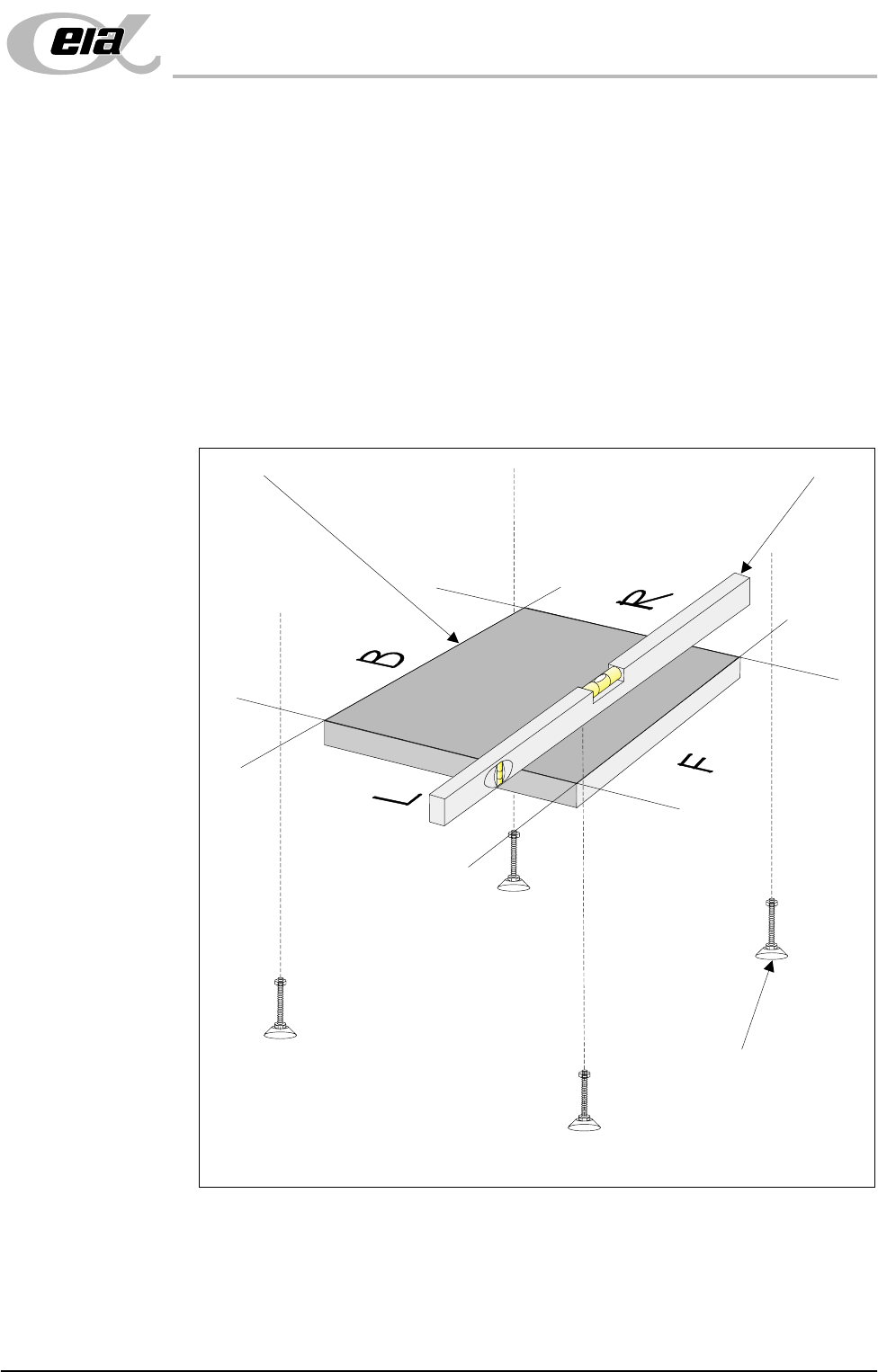
1. Place an engineering level on the tooling base plate facing Left (L) - Right
(R) or Back (B) - Front (F).
2. By carefully adjusting each of the four feet individually, level the machine
so that in each direction, Left (L) - Right (R) and Back (B) - Front (F), 0.004"
per foot (0.32mm/metre) is achieved.
3. Lock the feet using the locknuts on the adjusters.
Check that the machine height has not been disturbed. If machine height
requires further adjustment, carry out Machine Height and Machine Levelling
until the correct machine height and level is achieved.
Figure 5-11 Machine Levelling
Isometric View Showing Levelling of Tooling Base Plate
Tooling Base Plate
Engineering Level
Adjustable Mounting Feet
(4 positions)
MACHINE PREPARATION
SHOCK WATCHES
5.20 Installation Manual Chapter Issue 3 Jun 01
SHOCK WATCHES
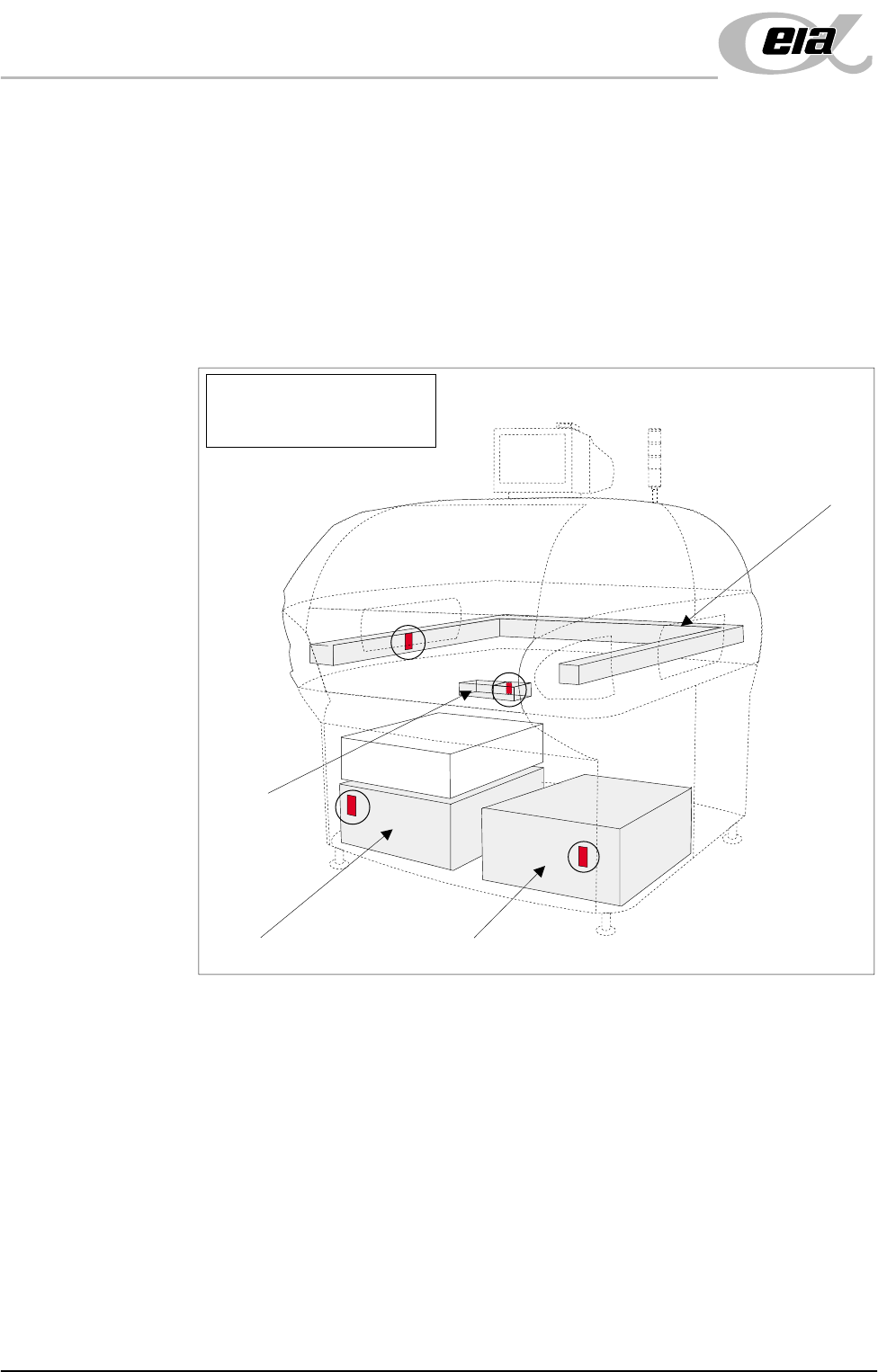
A self adhesive resettable shock watch (DEK Part No. 133517), is fitted in the
vertical plane on the machine in four places (Shock Watch Locations figure
refers).
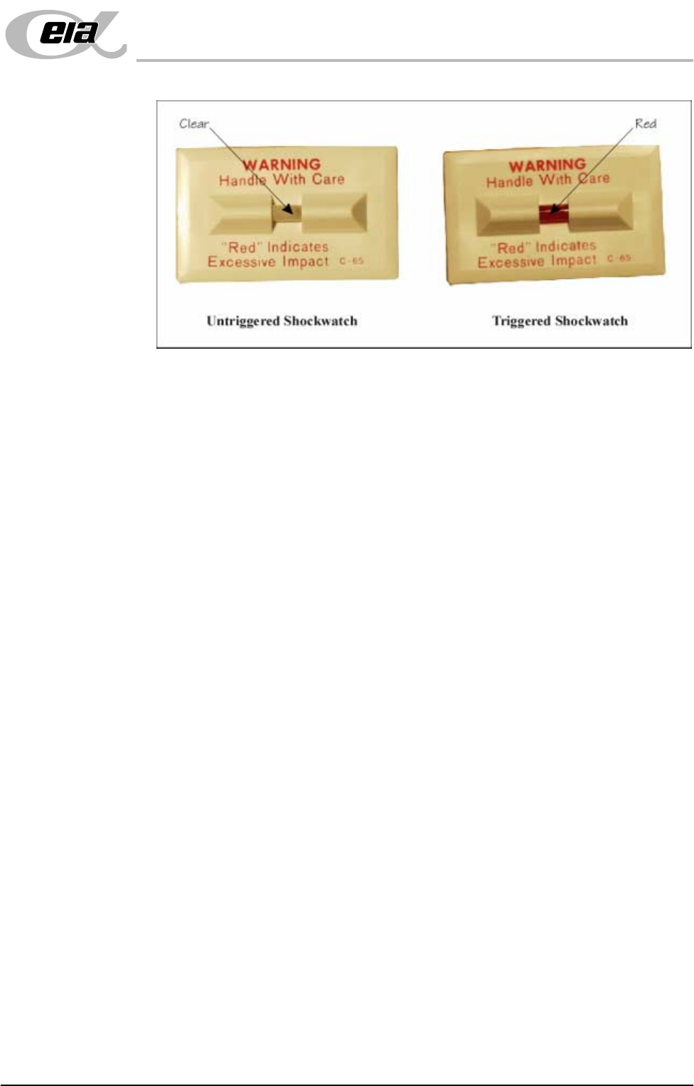
Check if the shock watches have been triggered, the indicator shows red, ('Drop
N Tell' Shockwatch figure overleaf refers).
NOTE
The machine should be fitted with four untriggered shock watches at all times.
Figure 5-12 Shock Watch Locations
Machine PC Machine Controller
Camera
Chase
NOTE
Shock Watches (4 positions)
shown circled
MACHINE PREPARATION
SHOCK WATCHES
Chapter Issue 3 Jun 01 Installation Manual 5.21
Figure 5-13 Drop N Tell Shockwatch
Chase Shock
Watch
If the chase shock watch has triggered, visually inspect the chase is level to the
table.
Camera Shock
Watch
If the camera shock watch has triggered, ensure that the camera is secure and
level on the camera mount (refer to Technical Reference Manual).
Machine PC Shock
Watch
If the machine PC shock watch has triggered, visually inspect the inside of the
PC and ensure that the cards are seated correctly.
Machine
Controller Shock
Watch
If the machine controller shock watch has triggered, visually inspect the machine
controller to ensure that the cards are seated correctly.
Shock Watch
Replacement
On completion of corrective action, replace any triggered shock watches.
NOTE
The machine should be fitted with four untriggered shock watches at all times.