ELA Installation.pdf - 第57页
POWER UP SEQUENCE MACHI NE POWE R UP SEQ UENC E Chapter Issu e 3 Jun 01 Installati on Manua l 6.9 Blue USC T o enable the blue under screen clea ner carry out the following: 1. Select Maint. (F8). 2. Select Set Prefs (F5…
POWER UP SEQUENCE
MACHINE POWER UP SEQUENCE
6.8 Installation Manual Chapter Issue 3 Jun 01
E Stop Loop
Operation
12.Carry out the following procedure for E Stop loop operation check:
a. Restore the DEK 265 program.
b. Select Diagnost (F6).
c. The Module Diagnostics Page is displayed with the system error message,
‘System Power Down’ superimposed on top of it.
d. Press the System button to enable system power.
13.Check E Stop loop operation as detailed in the table.
14.On completion of E Stop loop check, exit from the Diagnostics module.
15.Press the System button.
Screen Clean Function Check (if fitted)
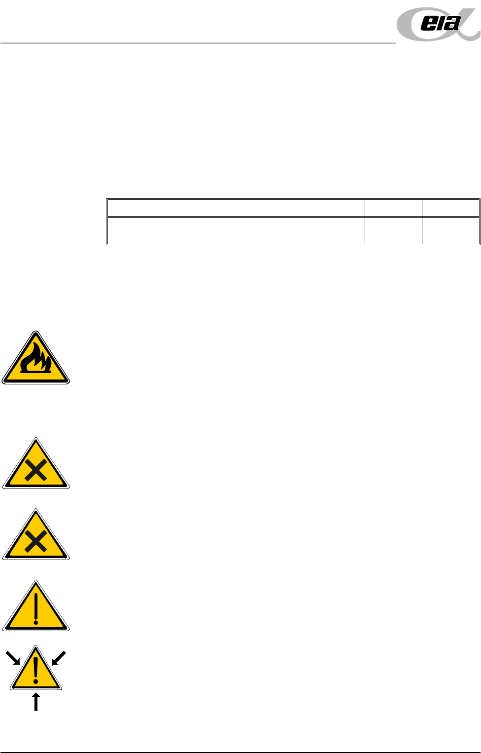
WARNING
RECOMMENDED SOLVENTS. ANY SOLVENTS USED MUST
COMPLY WITH LOCAL ENVIRONMENTAL GUIDELINES. DEK
RECOMMEND USING SOLVENTS THAT ARE
ENVIRONMENTALLLY FRIENDLY, IE CFC FREE AND WATER
BASED. SOLVENTS USED MUST HAVE FAST EVAPORATION
RATES AND FLASHPOINT SPECIFICATIONS GREATER THAN
39ºC.
WARNING
SOLDER PASTE AND SOLVENTS. WHEN USING OR HANDLING
ANY SOLDER PASTE OR SOLVENT FORMULATION THE
MANUFACTURERS’ RECOMMEND SAFETY PRECAUTIONS MUST
BE STRICTLY ADHERED TO.
WARNING
PROTECTIVE CLOTHING. APPROVED PROTECTIVE CLOTHING
SHOULD BE WORN BY SOLDER PASTE AND SOLVENT
HANDLERS AT ALL TIMES TO ELIMINATE FUME INHALATION,
EYE CONTACT, SKIN CONTACT AND INGESTION.
WARNING
SOLVENT SOLUTION. DO NOT MIX SOLVENT SOLUTIONS.
FLUSH THE SOLVENT TANK THOROUGHLY WHEN CHANGING
TO A DIFFERENT SOLVENT SOLUTION.
WARNING
SOLVENT SPRAY. THE UNDERSCREEN CLEANER SPRAYS A FINE
JET OF SOLVENT SOLUTION ON TO THE CLEANER. APPROVED
PROTECTIVE CLOTHING SHOULD BE WORN.
Detail Accept Reject
Check the correct operation of all components of the E Stop
loop, ie E Stop buttons, covers and external E Stop if fitted.
POWER UP SEQUENCE
MACHINE POWER UP SEQUENCE
Chapter Issue 3 Jun 01 Installation Manual 6.9
Blue USC To enable the blue under screen cleaner carry out the following:
1. Select Maint. (F8).
2. Select Set Prefs (F5).
3. Select F10 function key on the keyboard, type bluon and select Enter.
4. Set up the machine and filtration units as shown in the table.
5. Press Open Cover (F2) and raise the machine shutter.
6. Remove the solvent tank cap and add solvent to the tank using a funnel.
Replace the cap.
7. With the shutter raised, the menu bar displays the Prime Paper and Prime
Solvent options. Select Prime Solvent (F6) and when prompted press the
two control buttons until the paper is wet, (this may take several attempts
before solvent is sprayed onto the paper).
8. Select Prime Paper (F5) and when prompted press the two control buttons
simultaneously to feed a fresh area of dry paper over the solvent dispense
pipe ensuring that the paper feeds correctly.
9. Lower the machine shutter, press the System button and select Exit (F8).
Vortex USC To enable the Vortex under screen cleaner carry out the following:
1. Select Maint. (F8).
2. Select Set Prefs (F5).
3. Select F10 function key on the keyboard, type vorton and select Enter.
4. Set up the machine and filtration units as shown in the table.
5. Press Open Cover (F2) and raise the machine shutter and lower the drop
down panel.
6. Remove the solvent tank cap and add solvent to the tank using a funnel.
Replace the cap.
Vacuum Non Vacuum
Check the filtration unit is ON,
air flow set to 10
Set the machine transport mode to:
LEFT to LEFT
Set Machine transport mode to:
LEFT to LEFT
Set clean mode to:
1 WET-1 DRY
Set the clean mode to:
WET/VAC WET/DRY
Vacuum Non Vacuum
Check the filtration unit is ON, air flow set to
Max
Set the machine transport mode to LEFT
to LEFT
Set Machine transport mode to LEFT to LEFT

POWER UP SEQUENCE
MACHINE POWER UP SEQUENCE
6.10 Installation Manual Chapter Issue 3 Jun 01
7. With the cover in the up position, the menu bar displays the Prime Solvent
options. Select Prime Solvent (F6) and when prompted press the two
control buttons until the cleaning cassette wet cell is impregnated with
solvent (this may take several attempts before solvent is sprayed onto the wet
cell).
8. Raise the drop down panel and lower the machine shutter, press the System
button and select Exit (F8).
Paste Dispenser Function Check (if fitted)
ProFlow Contact
Position Setup
For machines using ProFlow only, set up the contact height position as follows:
1. In Module Diagnostics Page select Rising Table.
2. Select Home Rising Table. Select Run Diagnost. Select Exit.
3. In Module Diagnostics Page select Camera Axes.
4. Select Home Camera X Axis. Select Run Diagnost.
5. Select Home Camera Y Axis. Select Run Diagnost. Select Exit.
6. In the Module Diagnostics Page select ProFlow.
7. Select Home ProFlow. Select Run Diagnost. Select Exit.
8. In the Module Diagnostics Page select Print Carriage.
9. Select Home Print Carriage. Select Run Diagnost.
10.Select Drive Carriage Using Jog Buttons. Using the jog buttons drive the
Print Carriage to the mid position of the stencil.
11. Load a stencil with an off centre image.
12. At the MMI select Exit to return to Module Diagnostics Page.
13.In the Module Diagnostics Page select ProFlow. Select Adjust on the Menu
Bar.
14.In the ProFlow Adjust Parameters select PFLOW CONTACT POS.
15.At the Menu Bar select Incr. or Decr. to set the Contact Position to 5.5mm.
16.Fit an empty transfer head to the ProFlow pressure mechanism. Remove the
cover.
NOTE
Ensure wipers and skis are fitted to the transfer head.
17.Position a 0.1mm shim on the stencil under the transfer head.
Detail Accept
Set the paste cartridge empty sensor to operate correctly using
the customers solder paste.