ELA Installation.pdf - 第60页
POWER UP SEQUENCE MACHINE POW ER UP S EQUENCE 6.12 Installati on Manua l Chapter Iss ue 3 Jun 01

POWER UP SEQUENCE
MACHINE POWER UP SEQUENCE
Chapter Issue 3 Jun 01 Installation Manual 6.11
18.In the Module Diagnostics Page select Drive System to Contact Height.
Select Run Diagnost.
NOTE
Correct contact height is when the shim is just held between the transfer head
wipers and stencil. At this position it is not possible to slide the shim
sideways past the transfer head skis. If correct contact height is not yet
achieved, carry out the following steps:
19.Select Adjust on the Menu Bar.
20.In the ProFlow Adjust Parameters select PFLOW CONTACT POS.
21.At the Menu Bar select Incr. or Decr. to increase or decrease the Contact
Position set height by 0.5mm (eg 5.0mm or 6.0mm). Select Exit.
NOTE
Normally the contact position is between the range of 4mm - 8mm (nomi-
nally 6mm).
22.In the Module Diagnostics Page select Drive System to Contact Height.
Select Run Diagnost.
23.Check if contact height is correct, (as detailed in NOTE above). If adjust-
ment is still required repeat Steps 19 to 22 varying the set position until
correct height is achieved.
24.On completion of contact height set up select Home ProFlow on Module
Diagnostics Page. Select Run Diagnost.
25.Remove shim.

POWER UP SEQUENCE
MACHINE POWER UP SEQUENCE
6.12 Installation Manual Chapter Issue 3 Jun 01
FOREIGN MACHINE INTERFACE
INTRODUCTION
Chapter Issue 3 Jun 01 Installation Manual 7.1
CHAPTER 7 FOREIGN MACHINE INTERFACE
INTRODUCTION
The Foreign Machine Interface (FMI) is an electrical means of communication
between the ELA machine and an adjacent machine, using electrical signals.
The signals are transferred using opto-couplers and relay contacts which keep
the machines electrically isolated.
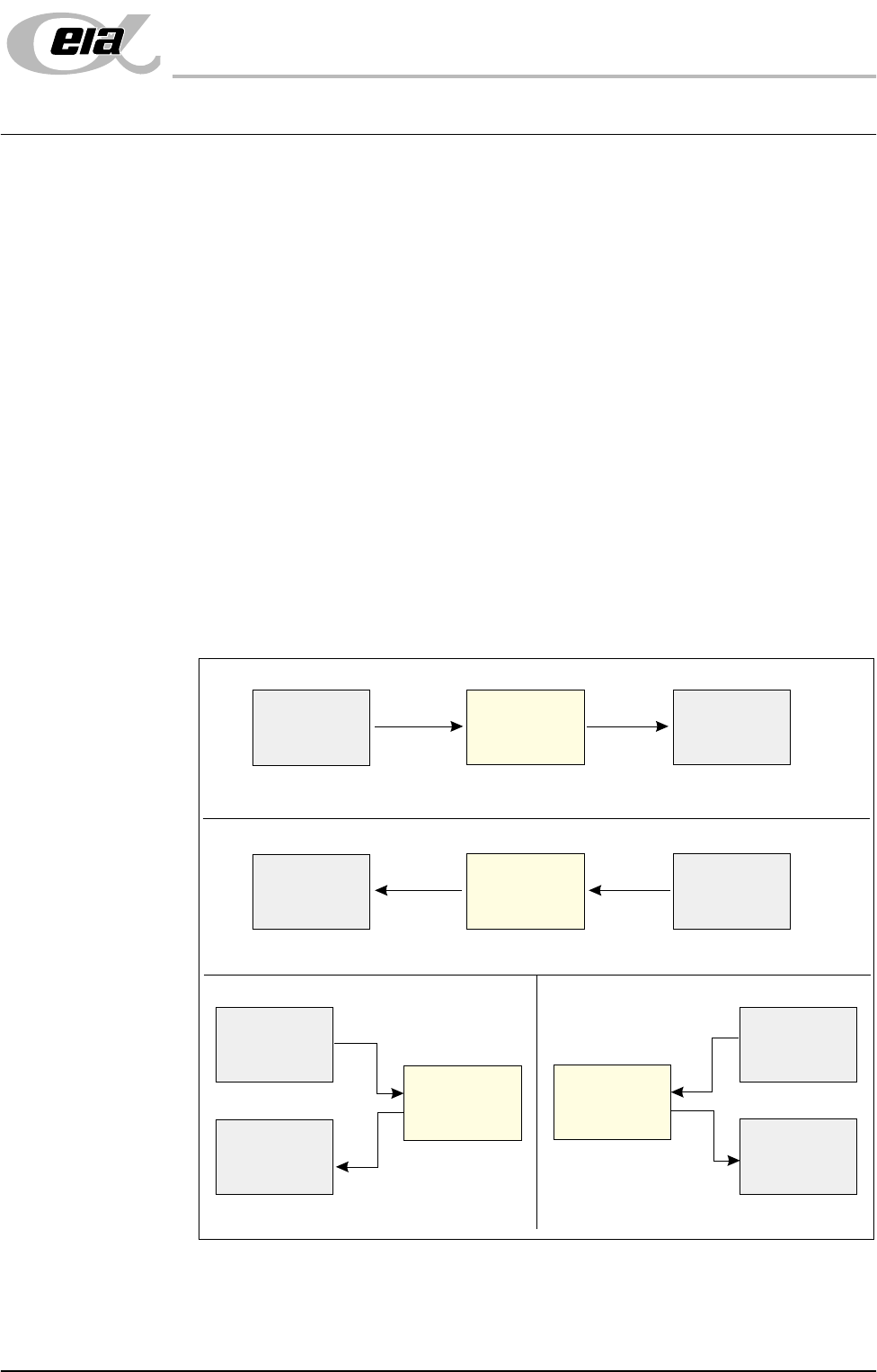
The adjacent machine can be upline or downline of the ELA machine in a left-
to-right or right-to-left board transfer arrangement, or it can be at one side of the
ELA machine in a left-to-left or right-to-right arrangement.
The ELA machine can interface with many different types of adjacent machine
which can be of any proprietary manufacture. The adjacent machine utilizes a
set of timing and control signals (protocols) for communication with other
machines. As there are many different protocols, DEK supplies a custom
designed FMI to suit the protocol for each type of adjacent machine.
The FMI hardware comprises:
• A Multi-Interface Unit (MIU) located on the rear of the machine.
• FMI loom connecting the FMI port, on the machine controller, to the MIU.
• Two interface cables, one cable for each adjacent machine.
Figure 7-1 Machine Arrangements for Board Transfers
Left to Right Board Transfers
Right to Left Board Transfers
Left to Left Board Transfers
Right to Right Board Transfers
Upline
Downline
Adjacent
Machine
Adjacent
Machine
ELA
Machine
Upline
Downline
Adjacent
Machine
Adjacent
Machine
ELA
Machine
Upline
Adjacent
Machine
Downline
Adjacent
Machine
Upline
Adjacent
Machine
Downline
Adjacent
Machine
ELA
Machine
ELA
Machine