ELA Installation.pdf - 第62页
FOREIGN MAC HINE INTERFAC E MODULE OVER VIEW 7.2 I nstallation M anual Chapter Issue 3 J un 01 MODULE O VER VIEW Figur e 7-2 Multi-Interface Unit M01SK1 Signal lines to and from the ELA machine from the upline machine. I…
FOREIGN MACHINE INTERFACE
INTRODUCTION
Chapter Issue 3 Jun 01 Installation Manual 7.1
CHAPTER 7 FOREIGN MACHINE INTERFACE
INTRODUCTION
The Foreign Machine Interface (FMI) is an electrical means of communication
between the ELA machine and an adjacent machine, using electrical signals.
The signals are transferred using opto-couplers and relay contacts which keep
the machines electrically isolated.
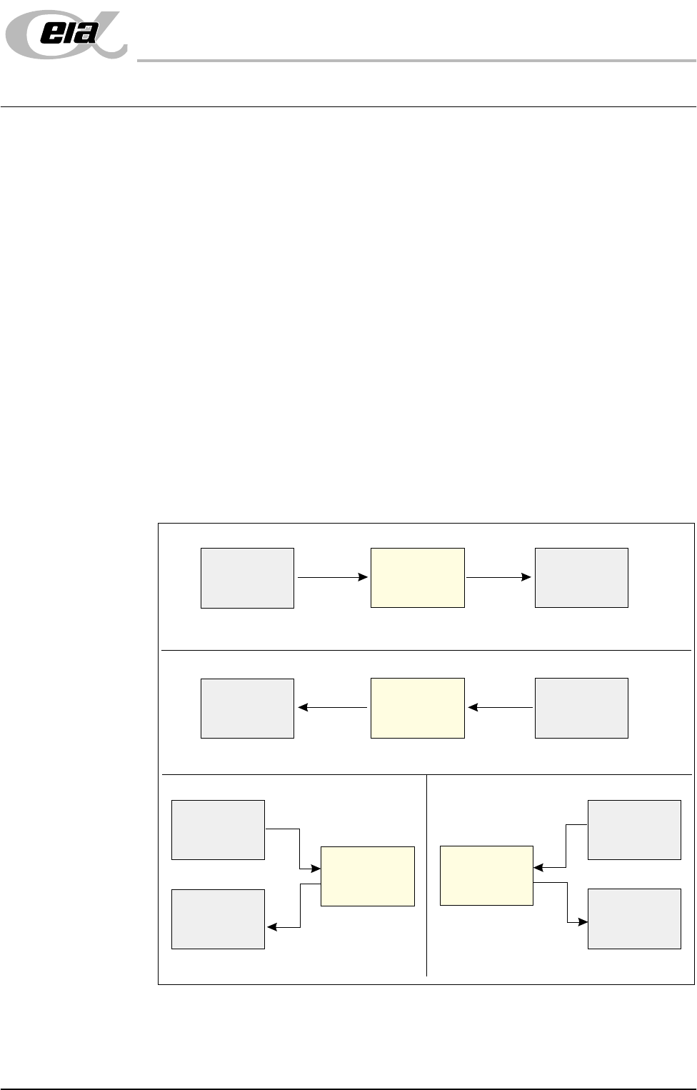
The adjacent machine can be upline or downline of the ELA machine in a left-
to-right or right-to-left board transfer arrangement, or it can be at one side of the
ELA machine in a left-to-left or right-to-right arrangement.
The ELA machine can interface with many different types of adjacent machine
which can be of any proprietary manufacture. The adjacent machine utilizes a
set of timing and control signals (protocols) for communication with other
machines. As there are many different protocols, DEK supplies a custom
designed FMI to suit the protocol for each type of adjacent machine.
The FMI hardware comprises:
• A Multi-Interface Unit (MIU) located on the rear of the machine.
• FMI loom connecting the FMI port, on the machine controller, to the MIU.
• Two interface cables, one cable for each adjacent machine.
Figure 7-1 Machine Arrangements for Board Transfers
Left to Right Board Transfers
Right to Left Board Transfers
Left to Left Board Transfers
Right to Right Board Transfers
Upline
Downline
Adjacent
Machine
Adjacent
Machine
ELA
Machine
Upline
Downline
Adjacent
Machine
Adjacent
Machine
ELA
Machine
Upline
Adjacent
Machine
Downline
Adjacent
Machine
Upline
Adjacent
Machine
Downline
Adjacent
Machine
ELA
Machine
ELA
Machine
FOREIGN MACHINE INTERFACE
MODULE OVERVIEW
7.2 Installation Manual Chapter Issue 3 Jun 01
MODULE OVERVIEW
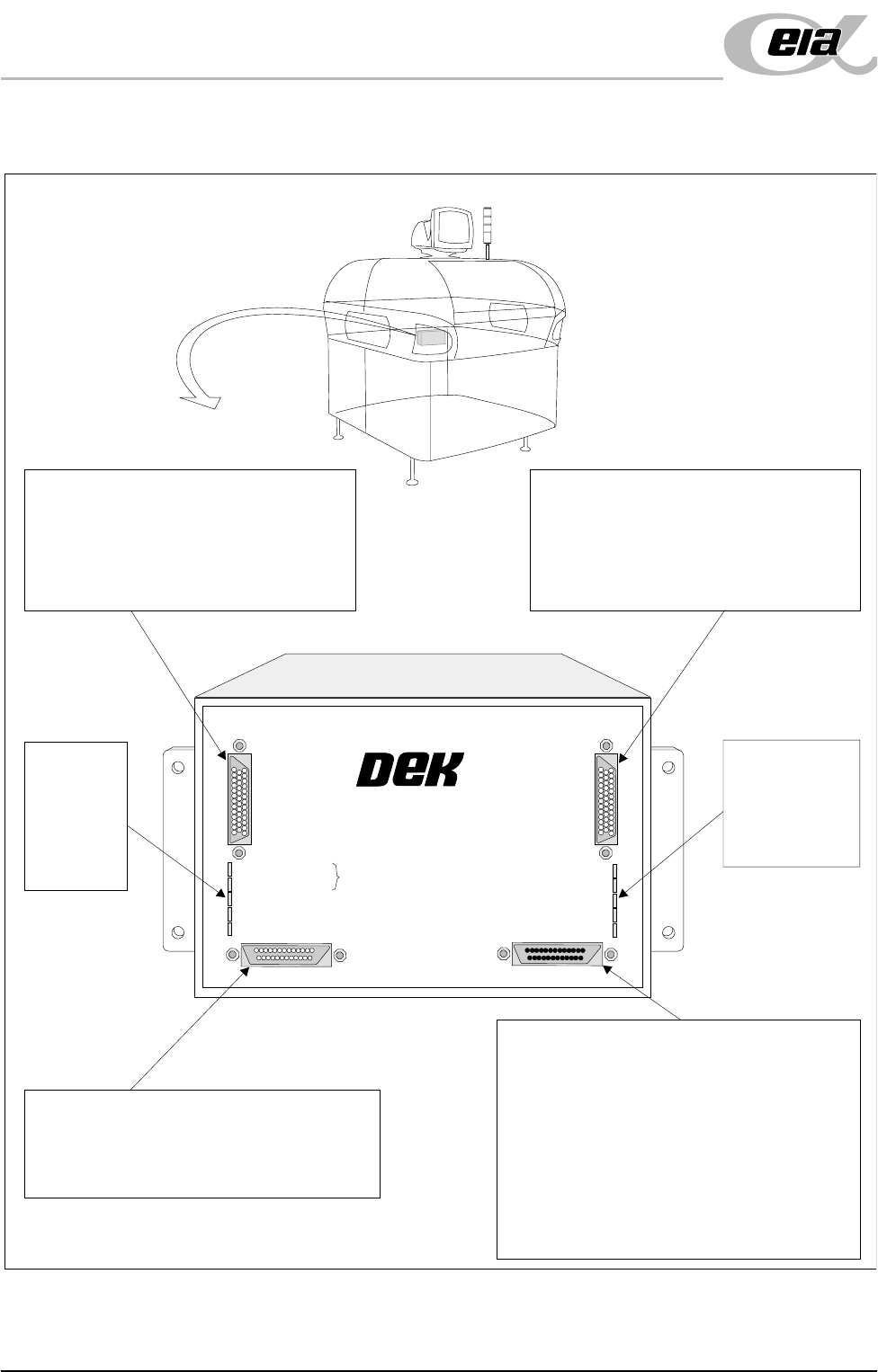
Figure 7-2 Multi-Interface Unit
M01SK1
Signal lines to and from the ELA machine
from the upline machine.
Inputs: Opto-isolated.
Outputs: Open collector output driver.
Relay switched.
M01SK2
Signal lines to and from the ELA machine
from the downline machine.
Inputs: Opto-isolated.
Outputs: Open collector output driver.
Relay switched.
M01SK3
The RS232 link is used for carrying out self
tests on the MIU only and has no function
on the ELA machine.
M01PL1
Power supplies.
Comms connections to this machine
Inputs to the ELA machine from interface -
1. Downline Ready
2. Upline Ready
3. Downline Available
Outputs from the ELA machine to interface -
1. Send Downline
2. Send Upline
3. DEK Available
LED Bank
LD2
Shows the
integrity of
the derived
supplies
LED Bank LD1
Indicates the
sequence of
events during
board transfers
+24V
+24V (E-STOP)
+12V
+5V
DOWNLINE READY
RS 232
DOWNLINE
UPLINE
DEK MACHINE
UPLINE READY
DOWNLINE AVAILABLE
SEND DOWNLINE
SEND UPLINE
DEK M/CN AVAILABLE
MULTI-INTERFACE UNIT
FROM
DEK
MACHINE
FOREIGN MACHINE INTERFACE
MULTI-INTERFACE UNIT
Chapter Issue 3 Jun 01 Installation Manual 7.3
MULTI-INTERFACE UNIT
The DEK Multi-Interface Unit (MIU) is a communications interface that allows
DEK Printing Machines to communicate with upline and downline board han-
dlers.
It simplifies the set up of the communications link between machines of different
manufacture by providing preprogrammed and programmable connections to
suit the interface protocol types commonly found within the board processing
industry.
The onboard, switch selectable, interface types are detailed later in this section.
Up to 16 interfaces can be specified for upline and downline handlers. The
upline machine can be of a different interface type to the downline machine.
Power supplies of +24V, +12V, +5V and 0V power the communications devices
of the upline and downline machines. Input signals to the MIU are opto-isolated.
Relay or open collector output driver signals are available for the MIU outputs.
A patching area routes patching link connections direct from upline to downline
as specified by any given protocol requirement.
The RS232 link is used for carrying out self tests on the MIU only and has no
function on the ELA machine.
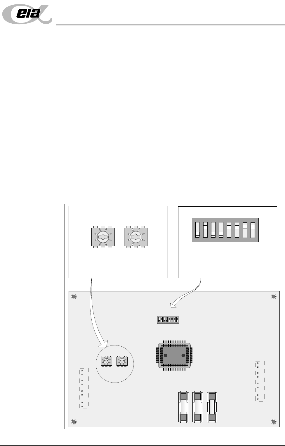
MIU Card Layout
Figure 7-3 MIU Card Layout
12345678
ON
0
8
2E
6A
C 4
0
8
2E
6A
C 4
ON
12345678
0
8
2E
6A
C 4
0
8
2E
6A
C 4
SW2 SW3
IC8
SW1
FS1 FS2 FS3
LD1
LD2
SW2 - Upline interface select switch
SW3 - Downline interface select switch
SW1 - RS232 function select switch
The setting of this switch is for carrying
out self tests on the MIU only and has
no affect on the ELA machine.
SW2 SW3
SW1