ELA Installation.pdf - 第63页
FOREIGN MACHINE INTERFA CE MULTI-INTE RFACE UNIT Chapter Issu e 3 Jun 01 Installati on Manua l 7.3 MUL TI-IN TERF A CE UNIT The DEK Multi-Interface Unit (MIU) is a communic ations interf ace that allo ws DEK Printing Mac…
FOREIGN MACHINE INTERFACE
MODULE OVERVIEW
7.2 Installation Manual Chapter Issue 3 Jun 01
MODULE OVERVIEW
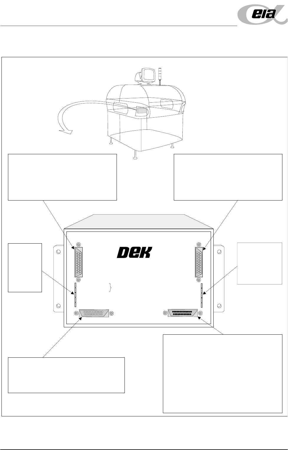
Figure 7-2 Multi-Interface Unit
M01SK1
Signal lines to and from the ELA machine
from the upline machine.
Inputs: Opto-isolated.
Outputs: Open collector output driver.
Relay switched.
M01SK2
Signal lines to and from the ELA machine
from the downline machine.
Inputs: Opto-isolated.
Outputs: Open collector output driver.
Relay switched.
M01SK3
The RS232 link is used for carrying out self
tests on the MIU only and has no function
on the ELA machine.
M01PL1
Power supplies.
Comms connections to this machine
Inputs to the ELA machine from interface -
1. Downline Ready
2. Upline Ready
3. Downline Available
Outputs from the ELA machine to interface -
1. Send Downline
2. Send Upline
3. DEK Available
LED Bank
LD2
Shows the
integrity of
the derived
supplies
LED Bank LD1
Indicates the
sequence of
events during
board transfers
+24V
+24V (E-STOP)
+12V
+5V
DOWNLINE READY
RS 232
DOWNLINE
UPLINE
DEK MACHINE
UPLINE READY
DOWNLINE AVAILABLE
SEND DOWNLINE
SEND UPLINE
DEK M/CN AVAILABLE
MULTI-INTERFACE UNIT
FROM
DEK
MACHINE
FOREIGN MACHINE INTERFACE
MULTI-INTERFACE UNIT
Chapter Issue 3 Jun 01 Installation Manual 7.3
MULTI-INTERFACE UNIT
The DEK Multi-Interface Unit (MIU) is a communications interface that allows
DEK Printing Machines to communicate with upline and downline board han-
dlers.
It simplifies the set up of the communications link between machines of different
manufacture by providing preprogrammed and programmable connections to
suit the interface protocol types commonly found within the board processing
industry.
The onboard, switch selectable, interface types are detailed later in this section.
Up to 16 interfaces can be specified for upline and downline handlers. The
upline machine can be of a different interface type to the downline machine.
Power supplies of +24V, +12V, +5V and 0V power the communications devices
of the upline and downline machines. Input signals to the MIU are opto-isolated.
Relay or open collector output driver signals are available for the MIU outputs.
A patching area routes patching link connections direct from upline to downline
as specified by any given protocol requirement.
The RS232 link is used for carrying out self tests on the MIU only and has no
function on the ELA machine.
MIU Card Layout
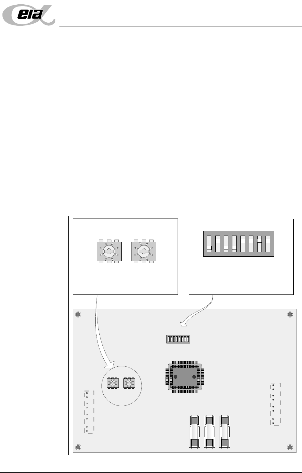
Figure 7-3 MIU Card Layout
12345678
ON
0
8
2E
6A
C 4
0
8
2E
6A
C 4
ON
12345678
0
8
2E
6A
C 4
0
8
2E
6A
C 4
SW2 SW3
IC8
SW1
FS1 FS2 FS3
LD1
LD2
SW2 - Upline interface select switch
SW3 - Downline interface select switch
SW1 - RS232 function select switch
The setting of this switch is for carrying
out self tests on the MIU only and has
no affect on the ELA machine.
SW2 SW3
SW1
FOREIGN MACHINE INTERFACE
MULTI-INTERFACE UNIT
7.4 Installation Manual Chapter Issue 3 Jun 01
Card Access To gain access to the three selector switches proceed as follows:
1. Remove connections to the MIU.
2. Remove the MIU from the bracket by releasing the four screws.
3. Remove the six MIU back plate screws.
Part Numbers and Settings
NOTE
DEK do not supply Dynapert, Philips or Europlacer interface cables.
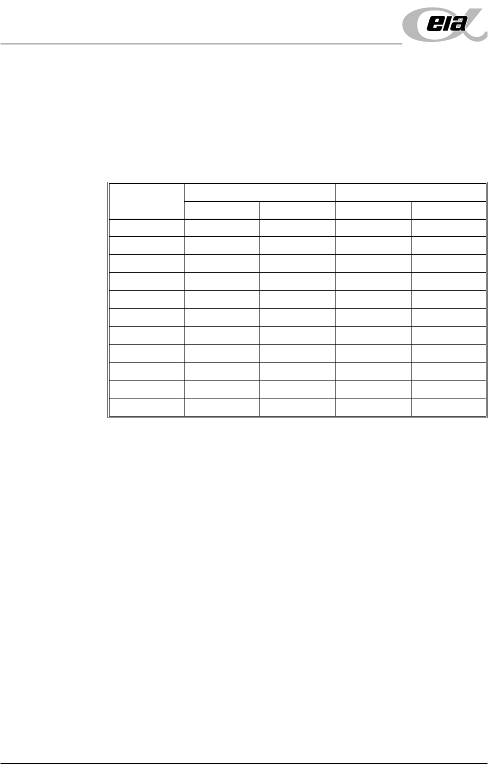
FMI Cables With the cables supplied, connect the upline and downline machines to the
screen printer MIU box connections. Cables should be routed down behind the
rear access panel.
Protocol
MIU Setting Cable Part Number
Upline SW2 Downline SW3 Upline Downline
Dynapert 0 0 N/A N/A
Philips 1 1 N/A N/A
SMEMA 2 2 131343 131345
Siemens 3 3 131335 131337
SMPI 4 4 131331 131333
TDK 5 5 131323 131325
Europlacer 6 6 N/A N/A
Fuji 7 7 126757 126758
Panasonic 7 7 131339 131341
Sanyo 8 8 146120 146119
Sanyo Flow Out 9 9 146120 146119