ELA Installation.pdf - 第67页
MACHIN E PER FORMAN CE MACHI NE CAPAB ILIT Y Chapter Issu e 4 Jun 01 Installati on Manua l 8.1 CHAP TE R 8 MACHINE PERFORMANCE MA CHIN E CAP ABIL ITY Load the product file named 265test1 from the hard disk and with a DEK…
FOREIGN MACHINE INTERFACE
PROCEDURE
7.6 Installation Manual Chapter Issue 3 Jun 01
7. When completed select Exit (F8). This saves the revised printer configura-
tion.
8. Select Setup (F6).
9. Select Mode (F1) until the mode displayed changes to No Print.
10.Select Exit (F8).
11.Ensure that the Upline and Downline Machines are connected and are
powered up, (E Stop loop connected if necessary).
12.Select Run (F1). This function key changes, to read Stop.
The screen printer requests a board from the upline machine and pass it through
the machine. The board stops at the sensor on the conveyor. On request from the
downline machine the board passes onto the external conveyor. When the sensor
is clear the screen printer requests another board from the upline machine and
the sequence repeats.
Selecting Stop ceases the sequence, changing the Stop key back to the Run key.
This shows that the interface is working between the screen printer and the
external machines.
Mode
Load
Data
Edit
data
Setup
squeegee
Change
Screen
Change
Tooling
Change
Language
Exit
Run Head
Paste
Load
Clean
screen
Adjust Setup Monitor Maint.
Mode
Load
Data
Edit
data
Setup
squeegee
Change
Screen
Change
Tooling
Change
Language
Exit
Mode
Load
Data
Edit
data
Setup
squeegee
Change
Screen
Change
Tooling
Change
Language
Exit
Run Head
Paste
Load
Clean
Screen
Adjust Setup Monitor Maint.
MACHINE PERFORMANCE
MACHINE CAPABILITY
Chapter Issue 4 Jun 01 Installation Manual 8.1
CHAPTER 8 MACHINE PERFORMANCE
MACHINE CAPABILITY
Load the product file named 265test1 from the hard disk and with a DEK
alignment board loaded ensure that the following parameters are correct:
• Screen - Calibration/Dry Align
• Squeegee - Length to suit board /ProFlow - Empty Transfer Head
• Front & Rear Print Speed - 25mm/sec (squeegees) / 70mm/sec (ProFlow)
• Front & Rear Pressure - 5kg (squeegees) / 3kg (ProFlow)
• ProFlow Paste Pressure - 2.2 bar
• Separation Speed - 1mm/sec.
• Under Board Clearance - 20mm
• Paste Dispense - 0
• Under Screen Rate - 0
• Transport Mode - Left to Left
• SPC Data Output Rate - Every Cycle
• SPC Data Mode - Disk
• SPC Format - Windows
• SPC Align Inspect Mode - Post Print
Use nine magnetic tooling pins to fully support the board, apply small amount
of paste or suitable lubricant (enough to lubricate squeegees). Record >100 full
machine cycles and setup QC-Cal program as follows:
1. Holding down the Windows button, press E on the keyboard and open
Explorer. If squeegees are fitted ensure the filter files sqy1.qcf and sqy2.qcf
are present in the directory structure C:\Prolink\QcCalc\Filters.
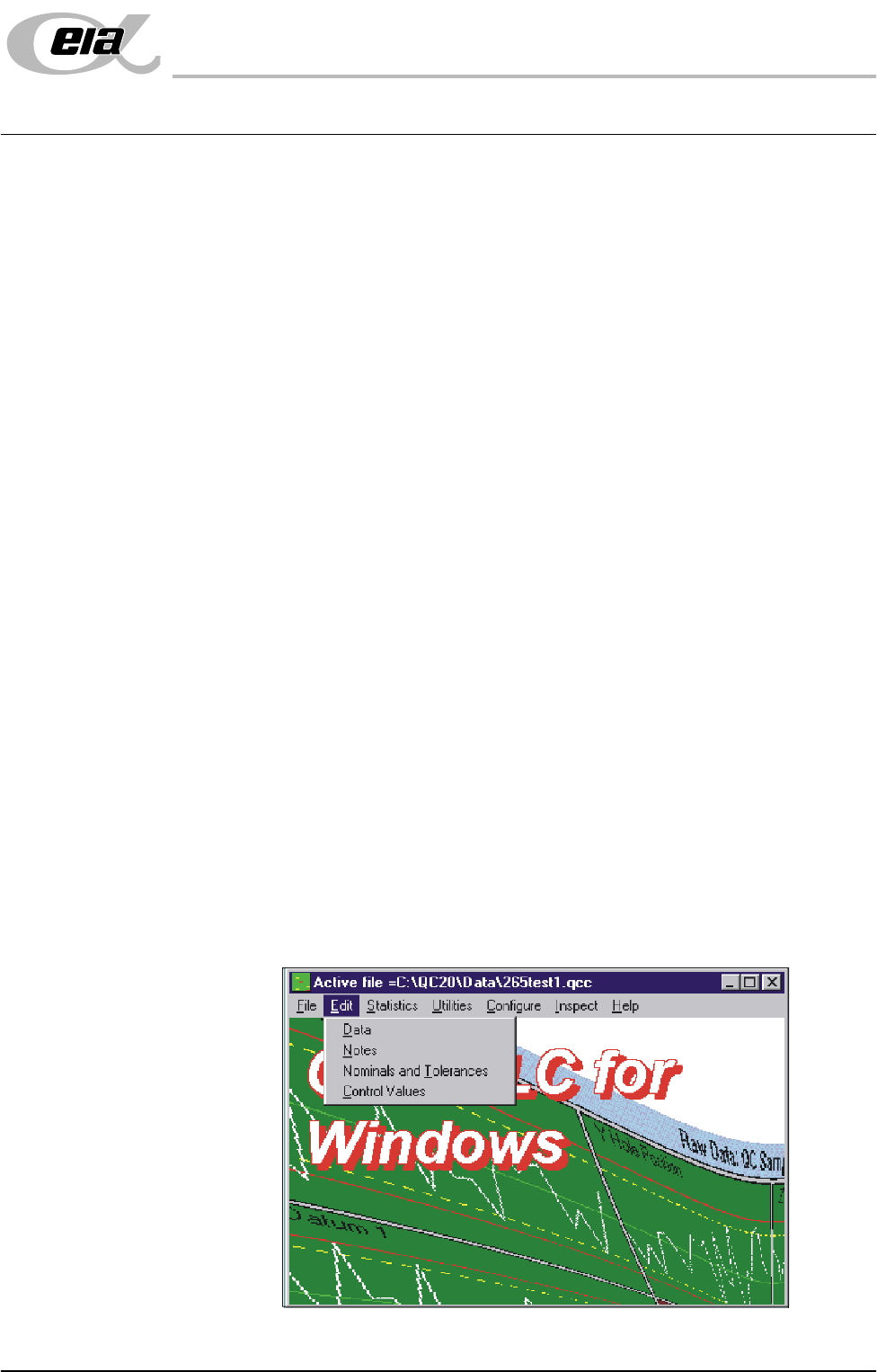
2. Start the QC-Cal program.
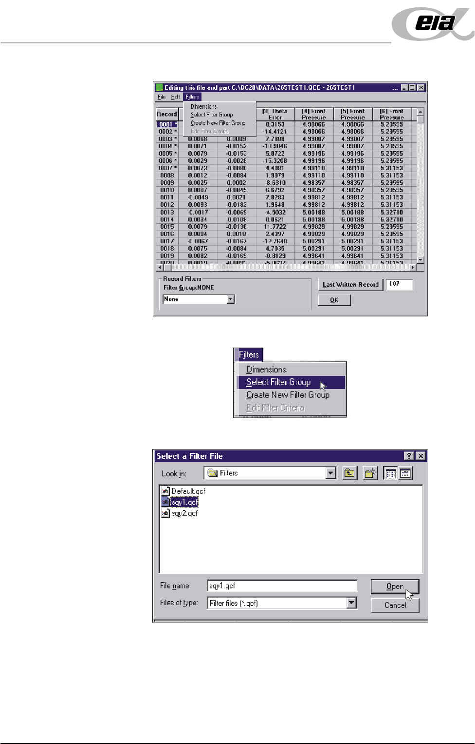
3. Select Edit, Data.
MACHINE PERFORMANCE
MACHINE CAPABILITY
8.2 Installation Manual Chapter Issue 4 Jun 01
4. Select Filters.
5. Select Select Filter Group.
6. Highlight sqy1.qcf file and select Open.