AG900+ and AG900+S Applicators Customer Product Manual.pdf - 第17页
AG − 900+ and AG900+S Applicators 13 2009 Nordson Corporation Part 1098464A Installation W ARNING! Allow only personnel with appropriate training and experience to operate or service the equipment. The use of untrained…
AG−900+ and AG900+S Applicators
12
Part 1098464A
2009 Nordson Corporation
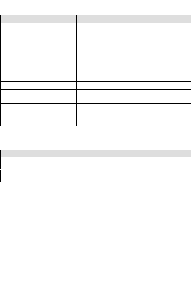
Specifications
Parameter Specification
Operating temperature C (F)
Unheated
Heated
0−50C (32−120 F)
204C (400F)
Maximum working pressure
210 bar (3000 psi) @ 121 C (250 F)
100 bar (1500 psi) @ >121 C (250 F)
Regulated output control
pressure
100 bar (1500 psi) @ 121 C (250 F)
Operating air pressure 4−6.89 bar (60−100 psi)
Viscosity range 1000−1 million cps
Electrical requirements (heated
applicators only)
220−240 VAC 50/60 Hz, 270W/ applicator,
100W/swivel
Weight kg (lb)
Heated
Cold
Regulated: 1.7 (3.8) Unregulated: 1.1 (2.4)
Regulated: 1.2 (2.65) Unregulated: .75 (1.65)
Physical Dimensions
Applicator Type With Regulator mm (in.) Without Regulator mm (in.)
Heated 140 H x 73 W x 107 D
(5.51 x 2.87 x 4.21)
140 H x 60 W x 67 D
(5.51 x 2.36 x 2.64)
Cold 140 H x 50 W x 107 D
(5.51 x 1.97 x 4.21)
140 H x 37 W x 67 D
(5.51 x 1.46 x 2.64)
AG−900+ and AG900+S Applicators
13
2009 Nordson Corporation
Part 1098464A
Installation
WARNING! Allow only personnel with appropriate training and
experience to operate or service the equipment. The use of
untrained or inexperienced personnel to operate or service the
equipment can result in injury, including death, to themselves and
others, and damage to the equipment.
The AG-900+/AG900+Smodular dispensing applicator is shipped fully assembled.
After unpacking:
1. Inspect the applicator assembly for dents, scratches, corrosion or other physical damage.
2. Heated units: inspect the cordset assemblies for damaged or bent pins or kinking in the
armor shielding.
3. Tighten and secure all fasteners.
Contact Nordson immediately to report damaged or missing items.
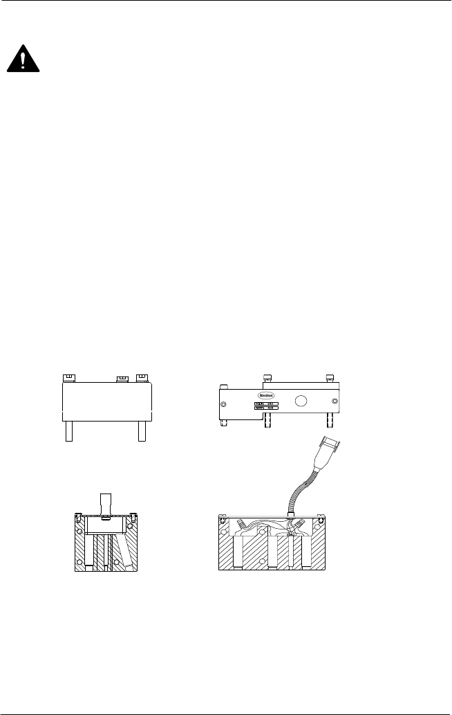
See Figure 2.The AG-900+/AG900+S applicator is mounted on a bracket, supplied by the
customer, that is secured to the applicator regulator module by using three M5 socket head
screws.
12
3
4
Figure 2: Socket Screws for Bracket Mounting with Adapter Block and Regulator
Heaters
1. Applicator bracket
2. Mounting bracket for heated regulator
3. Heater assembly for adapter block
4. Heater assembly for regulator
AG−900+ and AG900+S Applicators
14
Part 1098464A
2009 Nordson Corporation
Physical Dimensions (contd)
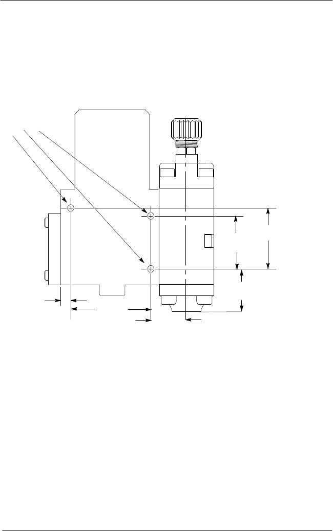
To install the AG-900+/AG900+S applicator, perform the following procedures:
1. See Figures 3 and . Remove the M5 mounting screws.
NOTE: On heated applicators, these screws also secure the heater assembly module
to the applicator.
38.7 mm
(1.525 in.)33 mm
(1.3 in.)
54.4 mm
(2.14 in.)
7.2 mm
(0.285 in.)
M5 Screw
24.1 mm
(.95 in.)
(1.1 in.)
28 mm
Figure 3: Mounting Dimensions for AG-900+/AG900+S Applicator with Regulator