AG900+ and AG900+S Applicators Customer Product Manual.pdf - 第30页
AG − 900+ and AG900+S Applicators 26 Part 1098464A 2009 Nordson Corporation Assembly (contd) 6. Install piston/cartridge assembly into module body . Carefully press on top of the cartridge to properly engage cartridge …
AG−900+ and AG900+S Applicators
25
2009 Nordson Corporation
Part 1098464A
Assembly
1. Install new o-rings and back-up ring on
piston/cartridge assembly.
2. AG900+ Module: See Figure 12. Install the new
needle assembly onto the piston/cartridge
assembly. Turn until the needle bottoms out
against the end of the piston shaft.
AG900+S Module: See Figure 11. Install the new
needle assembly onto the piston/cartridge
assembly. Turn until the needle bottoms out
against the end of the piston shaft.
NOTE: If the piston shaft is not fully seated
inside the needle assembly, the piston/cartridge
assembly with the needle assembly will not
properly seat in the applicator module and
nozzle, resulting in adhesive leaking
.
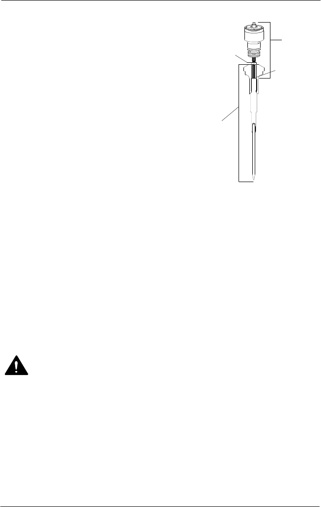
Figure
12: Piston/Cartridge
Assembly and Needle
Assembly
1. Piston/cartridge assembly
2. Needle Assembly
3. Jam nut
3. AG900+ Module: Tighten jam nut.
AG900+S Module: Tighten the needle against the
cartridge rod using two
5
/
16
in. open end
wrenches.
4. Clean module bore.
5. Apply o-ring lubricant to the module bore inside the
module body.
CAUTION! Apply o-ring lubricant to module body bore ONLY. Lubricating o-rings
directly or individual components causes back-up rings to become dislodged
when module is assembled.
2
3
Bottomed
out against
Piston Shaft
1
AG900+
AG−900+ and AG900+S Applicators
26
Part 1098464A
2009 Nordson Corporation
Assembly (contd)
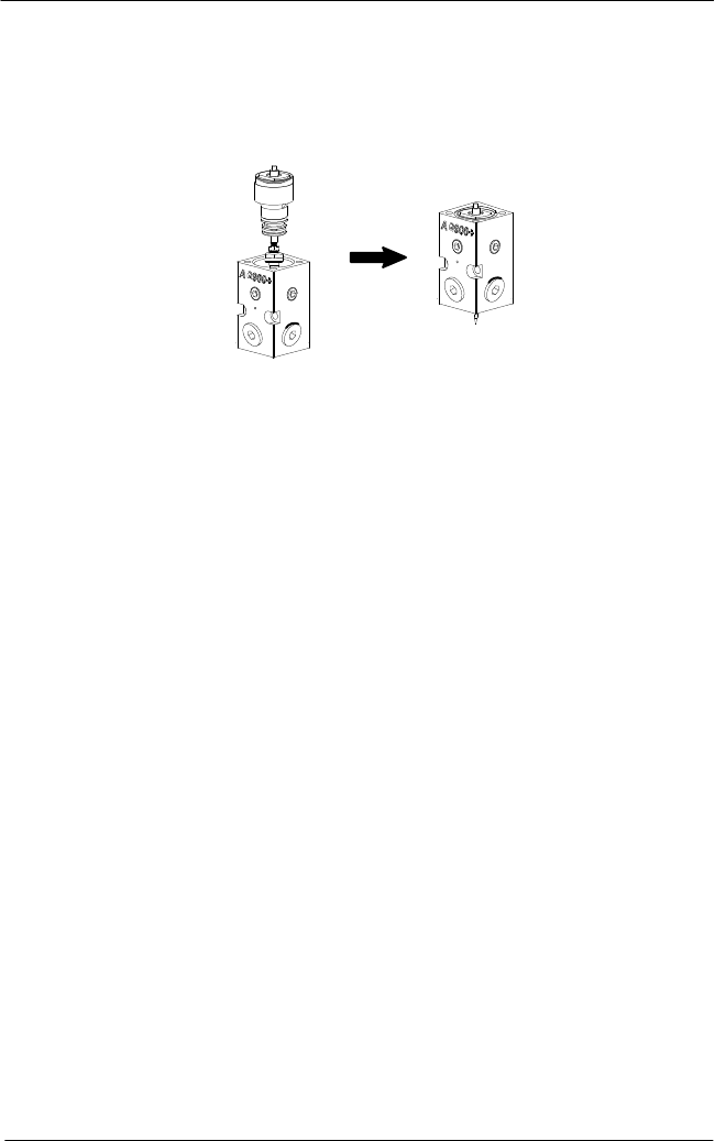
6. Install piston/cartridge assembly into module body. Carefully press on top of the cartridge
to properly engage cartridge o-rings into the module body bore.
NOTE: You will hear a small pop when the assembly seats in the module body.
Module
Body
Piston/Cartridge
Assembly with
Needle Assembly
Figure 13: Installing Piston/Cartridge with Needle Assembly
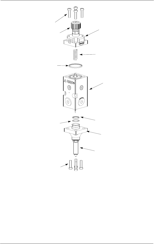
7. See Figure 14. Install new large o-ring (9) on top of piston cartridge.
8. Back out the stroke adjustment knob before installing the cap.
AG−900+ and AG900+S Applicators
27
2009 Nordson Corporation
Part 1098464A
2
3
9
4
6
8
5
1
1
7
10
Figure 14: AG-900+/AG900+S Applicator Assembly
1. Socket head screws
2. Air cap
3. Spring
4. Module body with piston/cartridge and needle
assemblies installed
5. O-ring
6. Nozzle flange
7. Nozzle (reference only)
8. Back-up ring
9. Large o-ring (top of
piston/cartridge assembly)
10. Stroke adjustment knob
9. Re-install spring(3) and cap (2). Insert two of the four socket head screws (1) in opposite
corners of the cap. Depress the cap and hand-tighten the two screws. Insert the
remaining screws into the cap and tighten all four screws to 7−8 ft.lbs.