Hybrid Calibration Offset Measurement and Correction Operation Manual.pdf - 第13页
H ybrid Cali bration Offset M easurement and Correction Operation Manual N XT V8.95 FUJI CORPORAT ION 13/18 Notes: 1. Push t he MONITO R button (ca mera pict ogram on t he NXT -3 touch screen) to display the v ision proc…
Hybrid Calibration Offset Measurement and Correction Operation Manual NXT V8.95
FUJI CORPORATION 12/18
Notes:
1. The jig parts are extremely small. Be careful not to drop them inside the machine
when performing this procedure.
2. If the above procedure is not performed, clear the error using the forced error
removal function in Accessory Software. When jig parts are on the nozzle, return
the jig parts to the jig part storage pocket on the jig stand and then use the forced
error removal function. (See chapter 9 for details on this function).
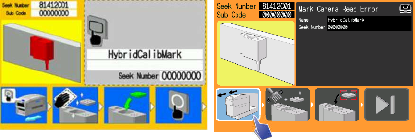
8.2. Stand mark vision processing errors
When the jig parts are placed on the stand, in order to calculate the placement
position, the marks on the stand are vision processed. Also in order to determine the
exact condition of the placed jig parts, the stand marks and the placed jig part marks
are vision processed. For these errors, where there is some problem with vision
processing, guidance instructs the operator to clean the stand and the jig parts.
NXT-2 operation panel NXT-3 operation panel
1. Push the OK button (press the pull out module pictogram for the NXT-3) and pull
the module out.
2. Clean the marks on the stand (if measurements are being performed with glass
jig parts, clean these too).
3. Set the parts in the part pockets on the stand.
4. Push [OK] (press the step pictogram for the NXT-3) to tell the machine that
maintenance (setting the jig parts) is complete.
5. Returning the module completes the procedure for clearing the error. The
machine waits for the START button to be pushed.
6. Push the START button to start hybrid calibration measurement (regardless of
the condition before the error, measurement is performed for all holders).
Hybrid Calibration Offset Measurement and Correction Operation Manual NXT V8.95
FUJI CORPORATION 13/18
Notes:
1. Push the MONITOR button (camera pictogram on the NXT-3 touchscreen) to
display the vision processing images. Press MONITOR (camera pictogram on the
NXT-3 touchscreen) again to return to the guidance screen.
2. The jig parts are extremely small. Be careful not to drop them inside the machine
when performing this procedure.
3. If the above procedure is not performed, clear the error using the forced error
removal function in Accessory Software. When jig parts are on the nozzle, return
the jig parts to the jig part storage pocket on the jig stand and then use the forced
error removal function. (See chapter 9 for details on this function).
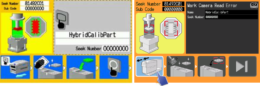
8.3. Jig part vision processing errors
When the jig parts are placed on the stand, the jig is vision processed in order to
correct for the exact position of the jig on the nozzle after pickup. For these errors,
where there is some problem with jig part vision processing, guidance instructs the
operator to clean the jig parts.
NXT-2 operation panel NXT-3 operation panel
1. Push the OK button (press the pull out module pictogram for the NXT-3) and
pull the module out.
2. Clean the jig parts.
3. Set the parts in the part pockets on the stand.
4. Push [OK] (press the step pictogram for the NXT-3) to tell the machine that
maintenance (setting the jig parts) is complete.
5. Returning the module completes the procedure for clearing the error. The
machine waits for the START button to be pushed.
6. Push the START button to start hybrid calibration measurement (regardless
of the condition before the error, measurement is performed for all holders).
Hybrid Calibration Offset Measurement and Correction Operation Manual NXT V8.95
FUJI CORPORATION 14/18
Notes:
1. Push the MONITOR button (camera pictogram on the NXT-3 touchscreen) to
display the vision processing images. Press MONITOR (camera pictogram on the
NXT-3 touchscreen) again to return to the guidance screen.
2. The jig parts are extremely small. Be careful not to drop them inside the machine
when performing this procedure.
3. If the above procedure is not performed, clear the error using the forced error
removal function in Accessory Software. When jig parts are on the nozzle, return
the jig parts to the jig part storage pocket on the jig stand and then use the forced
error removal function. (See chapter 9 for details on this function).
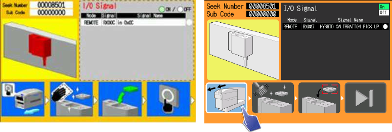
8.4. Stand vacuum errors
When the jig parts are placed on the stand, in order to secure the jig parts, the parts
are held down by suction from the stand. At this time, in order to confirm that the jig
parts are completely secured, the negative pressure is checked. For these errors, if
the negative pressure has not risen without a certain amount of time, guidance
instructs the operator to clean the jig parts.
If the negative pressure does not rise, the jig parts may not be placed correctly. If the
jig parts are not placed correctly, the results of vision processing may not be reliable.
It is thought that this problem can be avoided by cleaning the jig parts.
Also, if for some reason foreign material gets on the stand, parts may not be held
down correctly by the suction. It is thought that this problem can be avoided by
cleaning the stand.
NXT-2 operation panel NXT-3 operation panel
1. Push the OK button (press the pull out module pictogram for the NXT-3) and
pull the module out.
2. Clean the jig parts and marks on the stand.
3. Set the parts in the part pockets on the stand.
4. Push [OK] (press the step pictogram for the NXT-3) to tell the machine that
maintenance (setting the jig parts) is complete.