3OM-1064-001.pdf - 第17页
Check whether the internal part of the vacuum nozzle is stained or clogged. *1 If clogged, the vacuum nozzle may not be able to pick up a compo- nent. Refer to “Nozzle Stocker” in “6. Monthly Maintenance of Section 1 in …
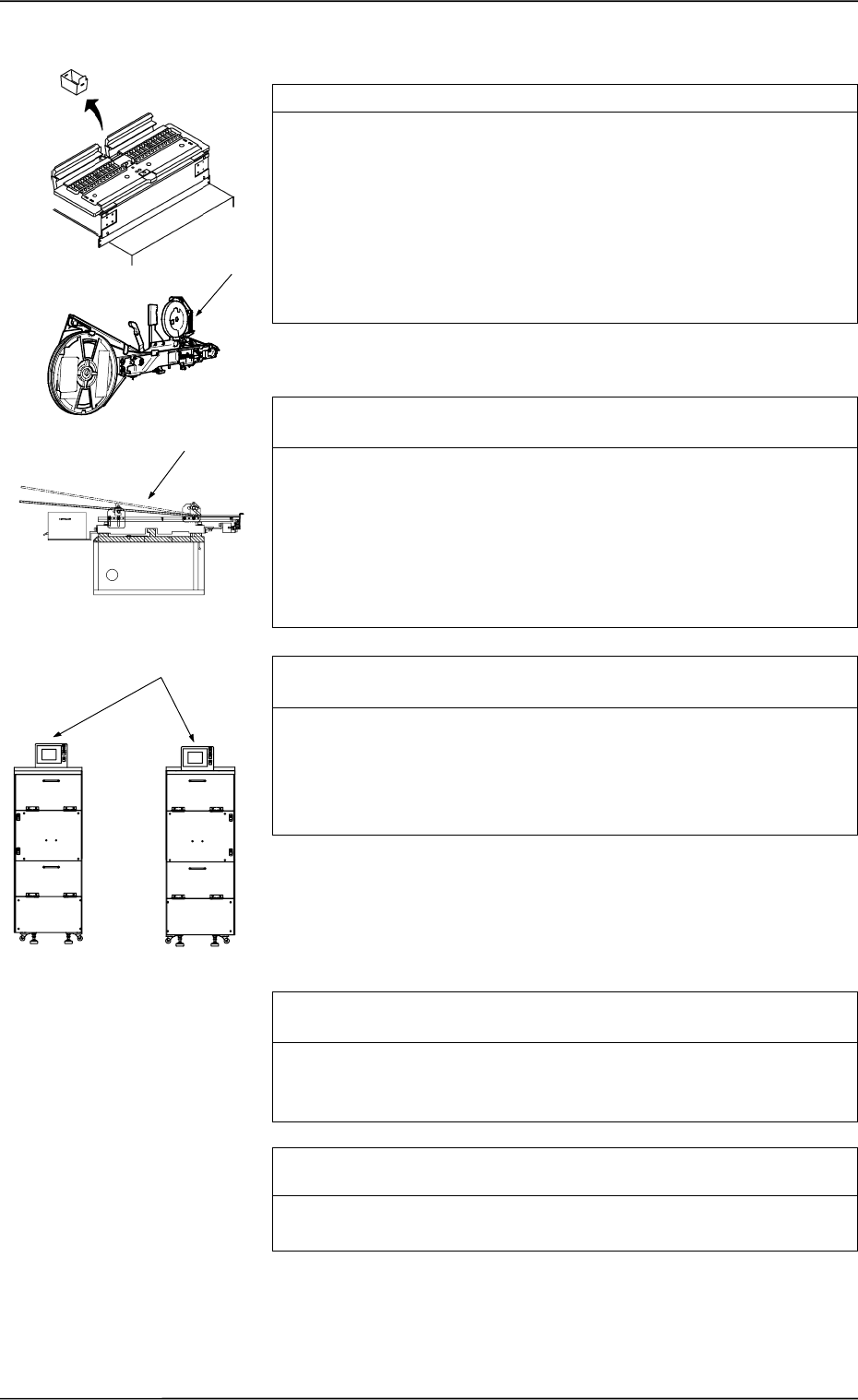
Check whether the error-caused tape feeder works normally. *1
Actually activate the feeder and check visually how it works.
•
Rotation of Reel Drive
•
Movement of Feed Lever
•
Tape Holding by Suppressor
•
Movement of Sprocket
•
Movement of Shutter Open/Close Lever
•
Tape Feed
•
Others
Check whether the error-caused vibratory stick feeder works nor-
mally. *2
Actually activate the feeder and check visually how it works.
•
Component Flow
•
Confirm that the tape feed time in the component library data is
proper.
•
Confirm that the escape action (action of air cylinder) takes place
normally.
•
Others
Check whether the error-caused multi-layer tray feeder (option)
works normally. *3
Actually activate the feeder and check visually how it works.
•
Tray Position
•
Transfer of Pallet from Elevator (how the pallet is pulled out
from the elevator)
•
Others
Check whether the pick-up position of the error-caused feeder is
proper. *4
Perform the teaching operation on the pick-up location at the “PICK-
UP LOCATION” display. (Hierarchical Sequence: “TEACH OFF-
SET” Display → “PICK-UP LOCATION” Display).
Check whether a tape feeder suitable for the selected compo-
nents is used. *5
Check the type and specifications of the tape feeder and confirm that
a tape feeder suitable for the selected tape is used.
*1
*2
*3
FP-5021R
FP-5021L
1.1.4 Frequently-Caused Pick-Up Errors on Specific Feeder
0005-002 1-8 Tg0248-PM-ER
1. Cause and Remedy of Simple Trouble
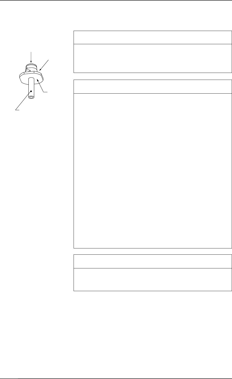
Check whether the internal part of the vacuum nozzle is stained
or clogged. *1
If clogged, the vacuum nozzle may not be able to pick up a compo-
nent.
Refer to “Nozzle Stocker” in “6. Monthly Maintenance of Section 1
in Volume 4” and inspect the nozzles. If necessary, clean them.
Check whether the frequently error-caused vacuum nozzle is
stained. *2
Dirty diffusion plate will cause a component recognition error or false
recognition.
If sebum or oil, etc., adheres to the surface of the diffusion plate of
the vacuum nozzle, note the followings and clean the surface.
(Otherwise, component recognition may become impossible.)
Prohibited Items
• Use of Organic Solvents, Rag, etc.
• Any Practice which may nick the diffusion plate
Recommended Cleaning: Use an ultrasonic cleaner and wash
the diffusion plate in water for 10 to
15 minutes or less.
Blow off moisture on the vacuum
nozzle, using compressed air.
If the nozzle is still dirty, consult our
sales personnel for details.
Note: Do not use any organic sol-
vent, a rag, etc.
Wipe off dirt accumulated on the nozzle end with a lens cleaning
cloth.
Refer to “Nozzle Stocker” in “6. Monthly Maintenance of Section 1
in Volume 4” for details.
Check whether the data for the frequently error-caused nozzle is
proper. *3
When the data for the nozzle length is not proper, components cannot
be picked up.
Check the data for the nozzle length in the nozzle data.
1.1.5 Frequently-Caused Pick-Up Errors on Specific Vacuum
Nozzle
Diffusion
Plate
*2
*1
Nozzle End
0005-002 1-9 Tg0248-PM-ER
1. Cause and Remedy of Simple Trouble

Check whether the component pick-up position is normal. *1
When the component pick-up position deviates from the correct one,
it may have come out of the component recognition range or the
vacuum nozzle may have interrupted image capture, causing a com-
ponent recognition error.
Or, vacuum may have leaked out during component picks, causing
an error such as deactivation of a vacuum sensor.
Perform the teaching operation on the pick-up location at the “PICK-
UP LOCATION” display. (Hierarchical Sequence: “TEACH OFF-
SET” Display → “PICK-UP LOCATION” Display).
Check whether the component recognition is performed normally.
*2
Confirm that there is no problem in the component recognition.
Refer to “1.2.3 Deterioration of Accuracy at Component Recognition
Camera Section of Section 1” for details and check whether the com-
ponent recognition is performed normally.
Check whether the selected components are deformed, making
it impossible for the vacuum sensor to detect them. *3
When the surface of components is not flat or is rough, the vacuum
leaks out, making it impossible for the vacuum sensor to detect such
components.
When it is designated to detect components by the vacuum sensor in
the component library, cancel the designation.
Check whether the vacuum sensor works normally. *4
Check how the vacuum sensor works.
Confirm that the vacuum sensor turns OFF when no component is
picked up and it turns ON when a component is picked up.
Check Procedure
(1) Open the “MANUAL SUBSYSTEM OPERATION” display. (Hi-
erarchical Sequence: “MANUAL MODE” Display → “MANUAL
SUBSYSTEM OPERATION” Display) Select the [BEAM-A AIR
SUPPLY] and [BEAM-B AIR SUPPLY] keys and press the
[MOVE] button to set to “OFF”.
(2) Select the [L**-AXIS VACUUM/BLOW] key and press the
[MOVE] button to set to “OFF”.
(3) Press the [I/O (DIO) DIAGNOSTIC] key. (Hierarchical Sequence:
“MAIN MENU” Display → “SPECIAL SEL.” Display → “DE-
VICE CHECK” Display → “INPUT CHECK” Display)
Then, press the [INP2-10] key and press the [NEXT PAGE] key to
open the 4th and 5th pages.
Confirm that the “L**-AXIS VACUUM SENSOR” is “OFF”.
(4) Open the “ZEROING OPERATION” display and zero the X/Y
beams. (Hierarchical Sequence: “MANUAL MODE” Display →
“ZEROING OPERATION” Display).
1.1.6 Normal Component Picks but Occurrence of Pick-Up
Errors
0005-002 1-10 Tg0248-PM-ER
1. Cause and Remedy of Simple Trouble