3OM-1064-001.pdf - 第20页
V acuum Pressure System Check whether the vacuum pressure is correctly adjusted. *1 Set the [P ASS/PLACE CHANGE] key to “PLACE” and turn of f all vacuum valves (LA1-, LA2-, LB1-, and LB2-axis vacuum/blow sole- noid valve…

(5) Open the “MANUAL AXIS OPERATION” display and move the
X/Y beams until they can be reached by hands. (Hierarchical Se-
quence: “MANUAL MODE” Display
“MANUAL AXIS OP-
ERATION” Display).
(6) Set the [OPERATION/SET UP] switch on the checked side to the
“SET UP” side.
(7) Press the [READY] button on the checked side and release the
electromagnetic locks of the supply cover and the safety bar.
(8) Open the supply cover on the checked side.
(9) Make a component picked up by hand and check how the vacuum
sensor is changed over.
Open the display described in Step (3) and confirm that the “L**-
AXIS VACUUM SENSOR” is changed from “OFF” to “ON”.
Otherwise, check whether an error occurs with another vacuum
nozzle or change over the vacuum nozzle and check for an error.
Check whether the vacuum filter of the placement head is clogged
when an error is found in the sensor after a nozzle change opera-
tion.
Notes: (a) When the vacuum nozzle is attached, the threshold level
of the vacuum sensor is automatically set.
To set the threshold level again, open the “MANUAL
NOZZLE CHANGE OPERATION” display and change
the nozzle manually.
Do not attach any vacuum nozzle by hand.
Refer to “9. MANUAL NOZZLE CHANGE OPERA-
TION Display of Section 4 in Volume 1” for details.
(b) When the sensor does not switch over normally even
though the vacuum filter is normal, it may be broken down.
In this case, consult our sales personnel for details.
Refer to “Head” in “6. Monthly Maintenance of Section
1 in Volume 4”and inspect the vacuum filter.
(c) Use a vacuum nozzle (inside diameter of pick-up hole: φ
2 mm or more) to inspect the vacuum filter.
0005-002 1-11 Tg0248-PM-ER
1. Cause and Remedy of Simple Trouble
Vacuum Pressure System
Check whether the vacuum pressure is correctly adjusted. *1
Set the [PASS/PLACE CHANGE] key to “PLACE” and turn off all
vacuum valves (LA1-, LA2-, LB1-, and LB2-axis vacuum/blow sole-
noid valves).
Confirm that "OFF" is set in the “STATUS” text boxes at the
“MANUAL SUBSYSTEM OPERATION” display.
Confirm that the vacuum pressure is -93 kPa (70 cmHg) or less.
When the vacuum pressure is too low, it is required to replace the
vacuum pump with a new one.
Consult our sales personnel for the detailed information on how to
replace or repair the vacuum pump.
Check whether the vacuum pump is producing any abnormal
sound. *2
Catch the sound of the vacuum pump and confirm that the sound is
not abnormal.
When abnormal sound is produced, consult our sales personnel for
the countermeasures.
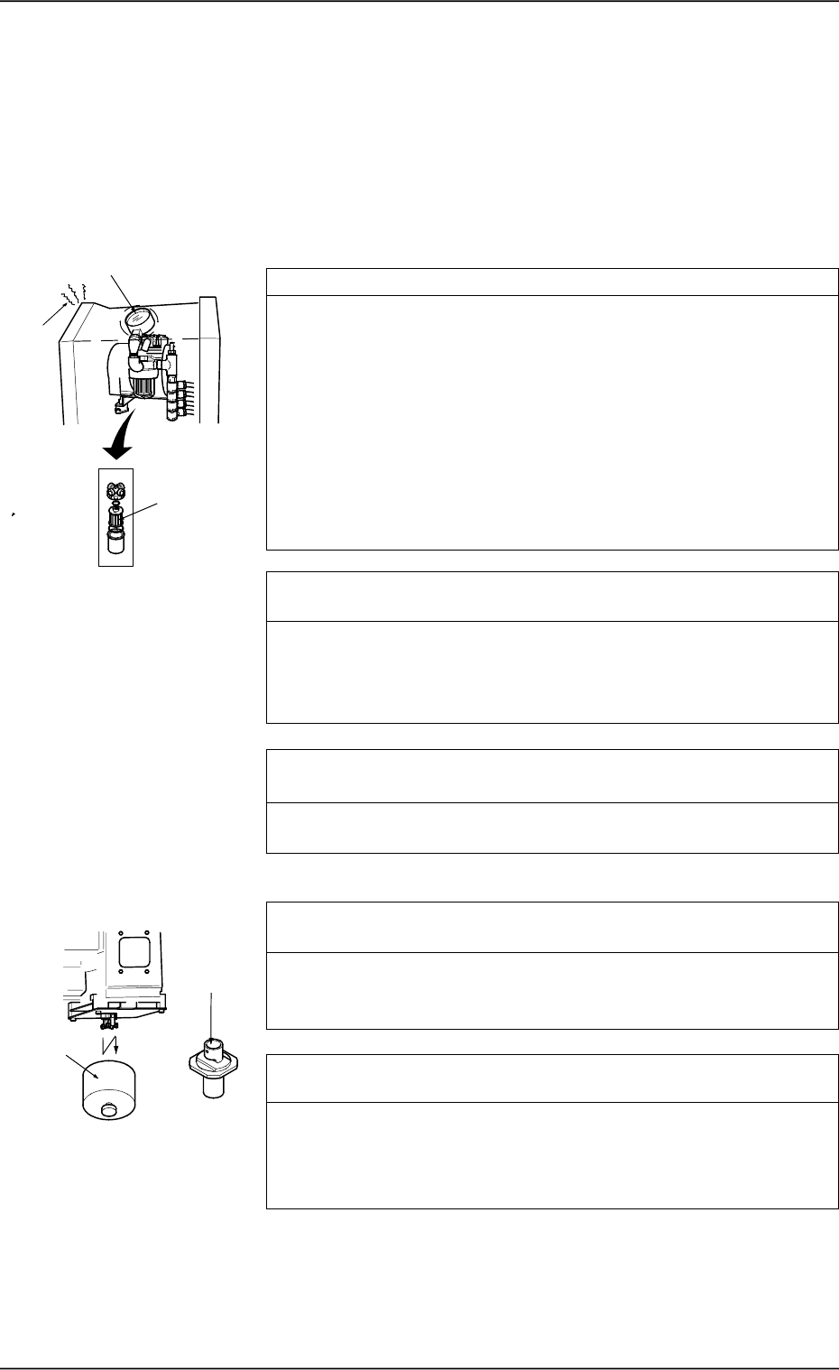
Check whether the filter of the vacuum pump is stained or clogged.
*3
Refer to “Vacuum Pressure System” in “8. Maintenance (Every 3
Months) of Section 1 in Volume 4” and inspect the filter.
Placement Head
Check whether the vacuum filter of the placement is stained or
clogged. *4
Refer to “Head” in “6. Monthly Maintenance of Section 1 in Volume
4” and inspect the filter. If necessary, replace the filter with a new
one.
Check whether the internal part of the vacuum nozzle is stained
or clogged. *5
If clogged, the vacuum nozzle may not be able to pick up a compo-
nent.
Refer to “Nozzle Stocker” in “6. Monthly Maintenance of Section 1
in Volume 4” and inspect the nozzles. If necessary, clean them.
1.2 Countermeasures against Deterioration of Place-
ment Accuracy
1.2.1 Deterioration of Accuracy in Vacuum System and Place-
ment Section
*1
*3
*2
*5
*4
0005-002 1-12 Tg0248-PM-ER
1. Cause and Remedy of Simple Trouble
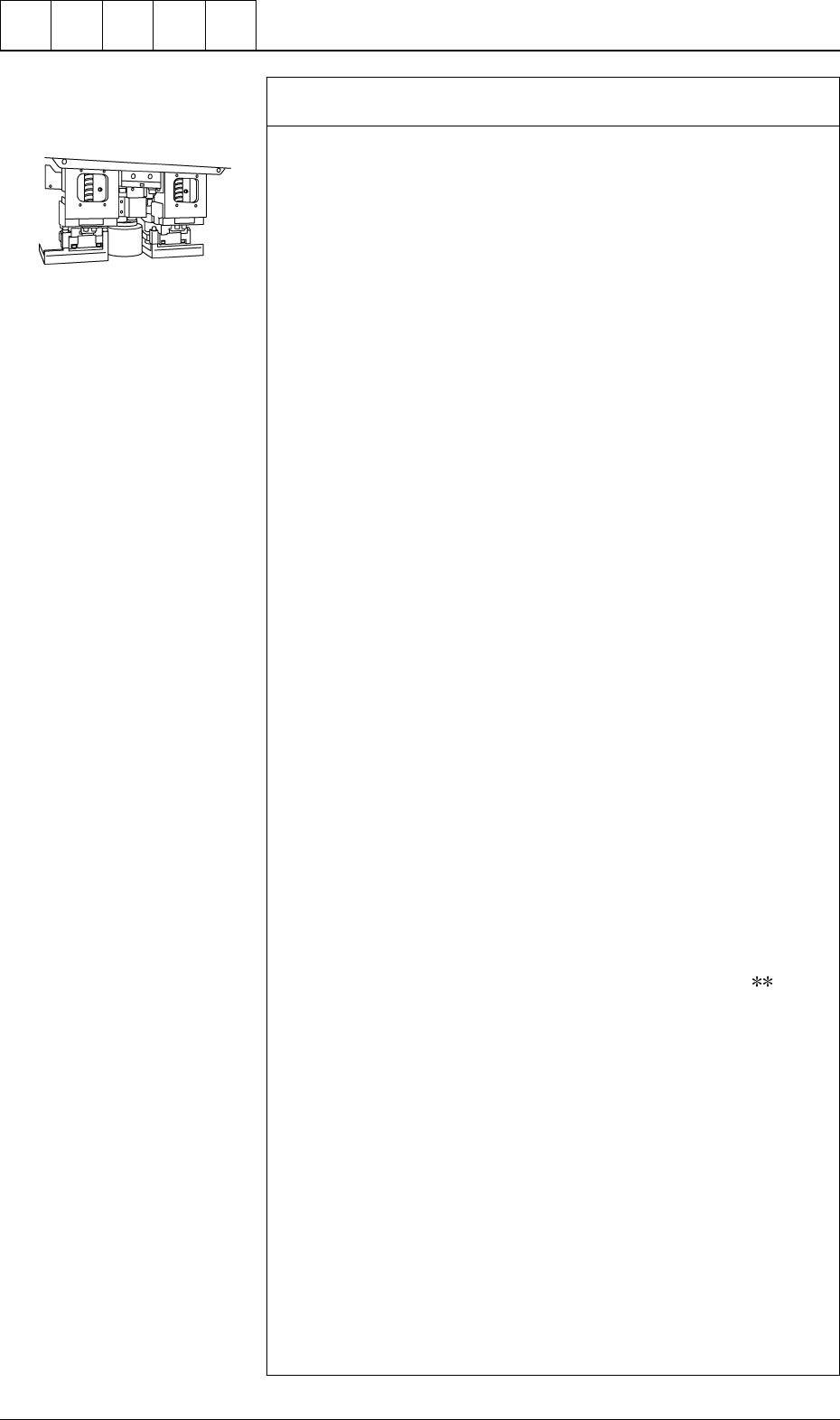
Check whether the vacuum/blow solenoid valves are changed
over normally. *6
Follow the two procedures described below.
Items Required for Confirmation
• MA04 Nozzle
• Small Piece of Paper (Approx. 10 × 10 mm)
Notes: (a) Sebum nor oil, etc., should not adhere to the surface
of the diffusion plate of the vacuum nozzle.
(b) Detach the feeder before confirmation.
Procedure for Confirmation (Air Supply: “OFF”)
(1) Open the “ZEROING OPERATION” display and zero the X/Y
beam. (Hierarchical Sequence: “MANUAL MODE” Display →
“ZEROING OPERATION” Display)
(2) Open the “MANUAL NOZZLE CHANGE OPERATION” dis-
play and replace the vacuum nozzle (the nozzle of the place-
ment head to be checked) with the MA04 one. (Hierarchical
Sequence: “MANUAL MODE” Display → “MANUAL
NOZZLE CHANGE OPERATION”Display)
(3) Open the “MANUAL SUBSYSTEM OPERATION” display.
Select the [BEAM-* AIR SUPPLY] or the [BEAM-B AIR SUP-
PLY] key and press the [MOVE] button to set to “OFF”. (Hier-
archical Sequence: “MANUAL MODE” Display → “MANUAL
SUBSYSTEM OPERATION” Display).
(4) Open the “ZEROING OPERATION” display and zero the X/Y
beams. (Hierarchical Sequence: “MANUAL MODE” Display
→ “ZEROING OPERATION” Display).
(5) Set the [OPERATION/SET UP] switch on the checked side to
the “SET UP” side.
(6) Press the [READY ] button on the checked side and release the
electromagnetic locks of the supply cover and the safety bar.
(7) Open the supply cover on the checked side.
(8) Open the “MANUAL SUBSYSTEM OPERATION” display and
press the [L**-AXIS VACUUM/BLOW] key to set the “BLOW”
mode. (Hierarchical Sequence: “MANUAL MODE” Display →
“MANUAL SUBSYSTEM OPERATION” Display)
(9) Put a small piece of paper on your palm and bring it close to the
end of the vacuum nozzle. Confirm that the paper does not move
at all.
Confirm that the paper is picked up when the [L
-AXIS
VACUUM/BLOW] key is pressed again to set the “VACUUM”
mode.
Procedure for Confirmation (Air Supply: "ON")
(1) Open the “ZEROING OPERATION” display and zero the X/Y
beam. (Hierarchical Sequence: “MANUAL MODE” Display →
“ZEROING OPERATION” Display).
(2) Open the “MANUAL NOZZLE CHANGE OPERATION” dis-
play and replace the vacuum nozzle (the nozzle of the place-
ment head to be checked) with the MA04 one. (Hierarchical
Sequence: "MANUAL MODE" Display → “MANUAL
NOZZLE CHANGE OPERATION” Display)
(3) Open the “MANUAL SUBSYSTEM OPERATION” display.
Select the [BEAM-A AIR SUPPLY] or the [BEAM-B AIR SUP-
PLY] key and press the [MOVE] button to set to “ON”. (Hierar-
chical Sequence: “MANUAL MODE” Display → “MANUAL
SUBSYSTEM OPERATION” Display).
Cut out the portion above to
use. (10 × 10 mm)
0005-002 1-13 Tg0248-PM-ER
1. Cause and Remedy of Simple Trouble