3OM-1064-001.pdf - 第22页
(4) Open the “MANUAL AXIS OPERA TION” display and move the X/Y beams until they can be reached by hands. (Hierarchical Sequence: “MANUAL MODE” Display “MANUAL AXIS OPERA TION” Display). (5) Set the [OPERA TION/SET UP] sw…
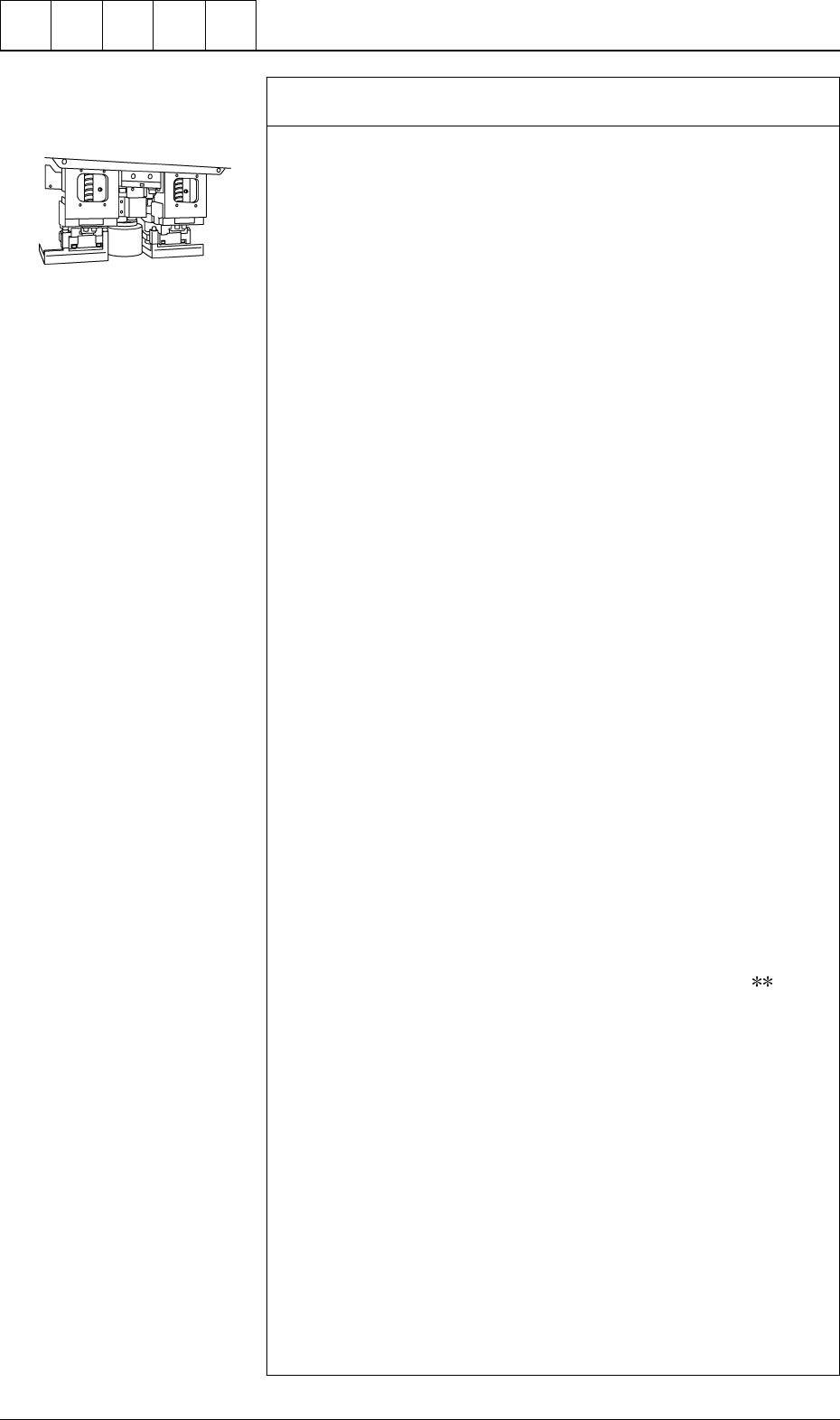
Check whether the vacuum/blow solenoid valves are changed
over normally. *6
Follow the two procedures described below.
Items Required for Confirmation
• MA04 Nozzle
• Small Piece of Paper (Approx. 10 × 10 mm)
Notes: (a) Sebum nor oil, etc., should not adhere to the surface
of the diffusion plate of the vacuum nozzle.
(b) Detach the feeder before confirmation.
Procedure for Confirmation (Air Supply: “OFF”)
(1) Open the “ZEROING OPERATION” display and zero the X/Y
beam. (Hierarchical Sequence: “MANUAL MODE” Display →
“ZEROING OPERATION” Display)
(2) Open the “MANUAL NOZZLE CHANGE OPERATION” dis-
play and replace the vacuum nozzle (the nozzle of the place-
ment head to be checked) with the MA04 one. (Hierarchical
Sequence: “MANUAL MODE” Display → “MANUAL
NOZZLE CHANGE OPERATION”Display)
(3) Open the “MANUAL SUBSYSTEM OPERATION” display.
Select the [BEAM-* AIR SUPPLY] or the [BEAM-B AIR SUP-
PLY] key and press the [MOVE] button to set to “OFF”. (Hier-
archical Sequence: “MANUAL MODE” Display → “MANUAL
SUBSYSTEM OPERATION” Display).
(4) Open the “ZEROING OPERATION” display and zero the X/Y
beams. (Hierarchical Sequence: “MANUAL MODE” Display
→ “ZEROING OPERATION” Display).
(5) Set the [OPERATION/SET UP] switch on the checked side to
the “SET UP” side.
(6) Press the [READY ] button on the checked side and release the
electromagnetic locks of the supply cover and the safety bar.
(7) Open the supply cover on the checked side.
(8) Open the “MANUAL SUBSYSTEM OPERATION” display and
press the [L**-AXIS VACUUM/BLOW] key to set the “BLOW”
mode. (Hierarchical Sequence: “MANUAL MODE” Display →
“MANUAL SUBSYSTEM OPERATION” Display)
(9) Put a small piece of paper on your palm and bring it close to the
end of the vacuum nozzle. Confirm that the paper does not move
at all.
Confirm that the paper is picked up when the [L
-AXIS
VACUUM/BLOW] key is pressed again to set the “VACUUM”
mode.
Procedure for Confirmation (Air Supply: "ON")
(1) Open the “ZEROING OPERATION” display and zero the X/Y
beam. (Hierarchical Sequence: “MANUAL MODE” Display →
“ZEROING OPERATION” Display).
(2) Open the “MANUAL NOZZLE CHANGE OPERATION” dis-
play and replace the vacuum nozzle (the nozzle of the place-
ment head to be checked) with the MA04 one. (Hierarchical
Sequence: "MANUAL MODE" Display → “MANUAL
NOZZLE CHANGE OPERATION” Display)
(3) Open the “MANUAL SUBSYSTEM OPERATION” display.
Select the [BEAM-A AIR SUPPLY] or the [BEAM-B AIR SUP-
PLY] key and press the [MOVE] button to set to “ON”. (Hierar-
chical Sequence: “MANUAL MODE” Display → “MANUAL
SUBSYSTEM OPERATION” Display).
Cut out the portion above to
use. (10 × 10 mm)
0005-002 1-13 Tg0248-PM-ER
1. Cause and Remedy of Simple Trouble
(4) Open the “MANUAL AXIS OPERATION” display and move
the X/Y beams until they can be reached by hands. (Hierarchical
Sequence: “MANUAL MODE” Display
“MANUAL AXIS
OPERATION” Display).
(5) Set the [OPERATION/SET UP] switch on the checked side to
the “SET UP” side.
(6) Press the [READY] button on the checked side and release the
electromagnetic locks of the supply cover and the safety bar.
(7) Open the supply cover on the checked side.
(8) Open the “MANUAL SUBSYSTEM OPERATION” display and
press the [L**-AXIS VACUUM/BLOW] key to set the
“VACUUM BLOW” mode. (Hierarchical Sequence: “MANUAL
MODE” Display
“MANUAL SUBSYSTEM OPERATION”
Display)
(9) Put a small piece of paper on your palm and bring it close to the
end of the vacuum nozzle. Confirm that air is blown to the pa-
per.
Confirm that the paper is picked up when the [L**-AXIS
VACUUM/BLOW] key is pressed again to set the “VACUUM”
mode.
Refer to “Section 4 Manual Mode Menus in Volume 1” for the
detailed information on each display.
Check whether the hoses of the X/Y beams and the placement
heads are crushed or have any holes. *7
Refer to the management data and check the hose of the placement
head which has caused low component pick-up rate.
• Confirm that the bundled or fixed part of the hoses is not crushed
or the vacuum is leaking.
• Confirm that the connected parts of the hoses are not crushed nor
the vacuum is not leaking.
• Confirm that the flat tubes are not bent.
• Confirm that no hose in the cable bearer has a hole due to friction
and mechanical wear.
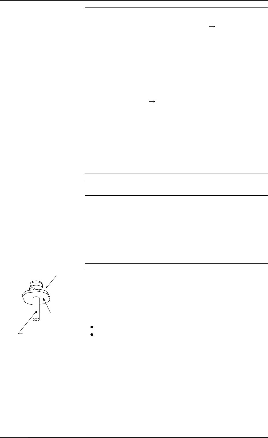
Check whether any vacuum nozzle is stained. *8
Dirty diffusion plate will cause a component recognition error or false
recognition.
If sebum or oil, etc., adheres to the surface of the diffusion plate of
the vacuum nozzle, note the followings and clean the surface.
(There is a possibility that components cannot be recognized.)
Prohibited Items
Use of Organic Solvents, Rag, etc.
Any Practice which may nick the diffusion plate
Recommended Cleaning: Use an ultrasonic cleaner and wash
the diffusion plate in water for 10 to
15 minutes or less.
Blow off moisture on the vacuum
nozzle, using compressed air.
If the nozzle is still dirty, consult our
sales personnel for details.
Note: Do not use any organic sol-
vent, a rag, etc.
Wipe off dirt accumulated on the nozzle end with a lens cleaning
cloth.
Refer to “Nozzle Stocker” in “6. Monthly Maintenance of Section 1
in Volume 4” and inspect the nozzles. If necessary, clean them.
Diffusion
Plate
*8
Nozzle End
0005-002 1-14 Tg0248-PM-ER
1. Cause and Remedy of Simple Trouble
Check whether the head rotational shaft rotates smoothly. *9
Confirm that the head rotational shaft rotates smoothly when turned
by hand.
Check whether the placement level is correct. *10
When a component is excessively pushed for placement or the vacuum
turns off before a component reaches the placement surface, it will be
placed incorrectly, deviating from the correct placement position.
Check the offset in the vertical (height) direction and the height data
in the component library data.
Check whether the device offset data is proper. *11
If the device offset data is not normal, component cannot be picked
up nor placed correctly.
Open the “OFFSET DATA” display and check each offset data. (Hi-
erarchical Sequence: “DATA EDIT” Display → “OFFSET DATA”
Display)
Open the “MANUAL SUBSYSTEM OPERATION” and “DEVICE
TEST” displays and check visually that each device moves to its cor-
rect position.
Note: Although each offset data can be taught at the “OFFSET
TEACH” display, it is required to re-teach a series of device
offset data. (Hierarchical Sequence: “SPECIAL SEL.” Dis-
play → “OFFSET TEACH” Display)
A special jig is also required for the teaching operations.
Whenever it is necessary to perform the teaching operations,
consult our sales personnel for details.
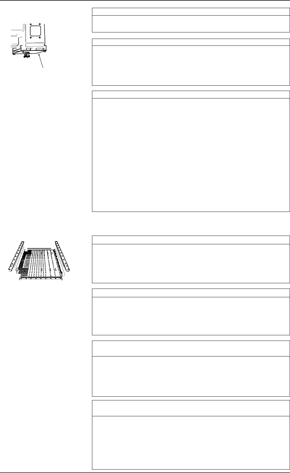
Check whether P.C.B. support pins are correctly set. *1
Check visually whether no problem has arisen in the location of the
P.C.B. support pins.
Especially, when components are placed on both sides of a P.C.B.,
confirm that no component on the back of the P.C.B. touches any
P.C.B. support pin.
Check whether the P.C.B. supporting plate moves normally. *2
Check visually whether no problem has arisen in the movement of
the P.C.B. supporting plate.
When the P.C.B. supporting plate does not move up (pushing) nor-
mally, a P.C.B. may deviate from its correct position during compo-
nent placement.
Check whether the set parameter as the conveyor width (com-
pared with the P.C.B. width) is correct. *3
If the conveyor width is not proper, P.C.B.’s cannot be transferred
smoothly, causing wrong P.C.B. positioning or positional deviation
of a P.C.B. due to vibrations (caused during placement).
Or, P.C.B.’s may not be pushed horizontally enough or positioned
correctly, causing positional deviation of a P.C.B. during placement.
Check whether the groove of the fixed chute or the bearing of the
movable chute is under abnormal condition. *4
If a foreign substance exists in the groove of the fixed chute, P.C.B.’s
cannot be positioned correctly, causing positional deviation of place-
ment. If a foreign substance is found in the groove of the fixed chute
or the bearing of the movable chute during P.C.B. transfer does not
work smoothly, P.C.B.’s cannot be transferred, causing wrong P.C.B.
positioning or positional deviation of a P.C.B. due to vibrations (caused
during placement).
*9
1.2.2 Deterioration of Accuracy in P.C.B. Positioning Section,
User Production P.C.B.’s, and Transfer Section
0005-002 1-15 Tg0248-PM-ER
1. Cause and Remedy of Simple Trouble