3OM-1064-001.pdf - 第237页
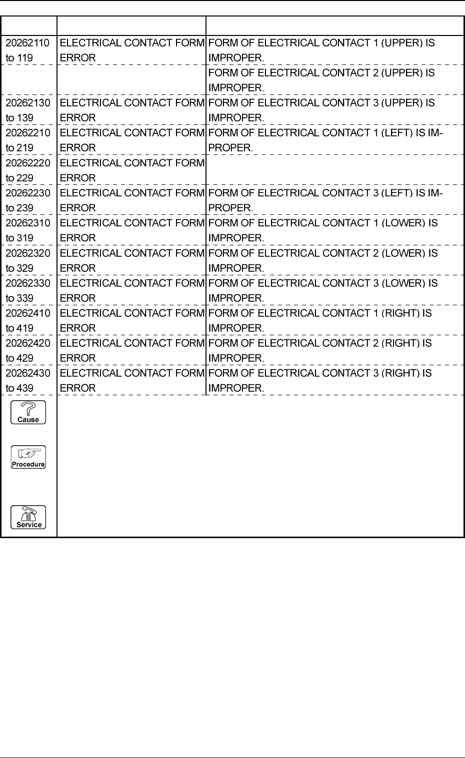
5. Component Recognition Error Code and List of Error Messages 0005-002 4-40 Tg0248-PM-ER Error Code Display A Display B FORM OF ELECTRICAL CONT ACT 2 (LEFT) IS IM- PROPER. 20262120 ELECTRICAL CONT ACT FORM to 129 ERROR …
5. Component Recognition Error Code and List of Error Messages
0103-003 4-39 Tg0248-PM-ER
Error Code Display A Display B
2025A110 ELECTRICAL CONTACT
to 119 LENGTH ERROR
Note: A represents “2” or “3”.
LENGTH OF ELECTRICAL CONTACT 1 (UPPER) EX-
CEEDS THE TOLERANCE.
2025A120 ELECTRICAL CONTACT
to 129 LENGTH ERROR
Note: A represents “2” or “3”.
LENGTH OF ELECTRICAL CONTACT 2 (UPPER) EX-
CEEDS THE TOLERANCE.
2025A210 ELECTRICAL CONTACT
to 219 LENGTH ERROR
Note: A represents “2” or “3”.
LENGTH OF ELECTRICAL CONTACT 1 (LEFT) EX-
CEEDS THE TOLERANCE.
2025A220 ELECTRICAL CONTACT
to 229 LENGTH ERROR
Note: A represents “2” or “3”.
LENGTH OF ELECTRICAL CONTACT 2 (LEFT) EX-
CEEDS THE TOLERANCE.
2025A130 ELECTRICAL CONTACT
to 139 LENGTH ERROR
Note: A represents “2” or “3”.
LENGTH OF ELECTRICAL CONTACT 3 (UPPER) EX-
CEEDS THE TOLERANCE.
2025A230 ELECTRICAL CONTACT
to 239 LENGTH ERROR
Note: A represents “2” or “3”.
LENGTH OF ELECTRICAL CONTACT 3 (LEFT) EX-
CEEDS THE TOLERANCE.
2025A310 ELECTRICAL CONTACT
to 319 LENGTH ERROR
Note: A represents “2” or “3”.
LENGTH OF ELECTRICAL CONTACT 1 (LOWER) EX-
CEEDS THE TOLERANCE.
2025A320 ELECTRICAL CONTACT
to 329 LENGTH ERROR
Note: A represents “2” or “3”.
LENGTH OF ELECTRICAL CONTACT 2 (LOWER) EX-
CEEDS THE TOLERANCE.
2025A330 ELECTRICAL CONTACT
to 339 LENGTH ERROR
Note: A represents “2” or “3”.
LENGTH OF ELECTRICAL CONTACT 3 (LOWER) EX-
CEEDS THE TOLERANCE.
2025A420 ELECTRICAL CONTACT
to 429 LENGTH ERROR
Note: A represents “2” or “3”.
LENGTH OF ELECTRICAL CONTACT 2 (RIGHT) EX-
CEEDS THE TOLERANCE.
2025A430 ELECTRICAL CONTACT
to 439 LENGTH ERROR
Note: A represents “2” or “3”.
LENGTH OF ELECTRICAL CONTACT 3 (RIGHT) EX-
CEEDS THE TOLERANCE.
2025A410 ELECTRICAL CONTACT
to 419 LENGTH ERROR
Note: A represents “2” or “3”.
LENGTH OF ELECTRICAL CONTACT 1 (RIGHT) EX-
CEEDS THE TOLERANCE.
(Cause 1) Is the electrical contact length correct?
(Reset Procedure in the case of Cause 1)
Reset Procedure
(1) Press the [ZERO] button to return all the axes to their original positions.
(2) Re-start.
(3) If the device can’t be re-started, contact our service personnel.
5. Component Recognition Error Code and List of Error Messages
0005-002 4-40 Tg0248-PM-ER
Error Code Display A Display B
FORM OF ELECTRICAL CONTACT 2 (LEFT) IS IM-
PROPER.
20262120 ELECTRICAL CONTACT FORM
to 129 ERROR
(Cause 1) This is the device’s self-diagnostic message.
(Reset Procedure in the case of Cause 1)
Reset Procedure
(1) Press the [CLEAR ALARM] key and the buzzer stops sounding.
(2) Press the [ZERO] button to return all the axes to their original positions.
(3) Re-start.
(4) If the device can’t be re-started, contact our service personnel.
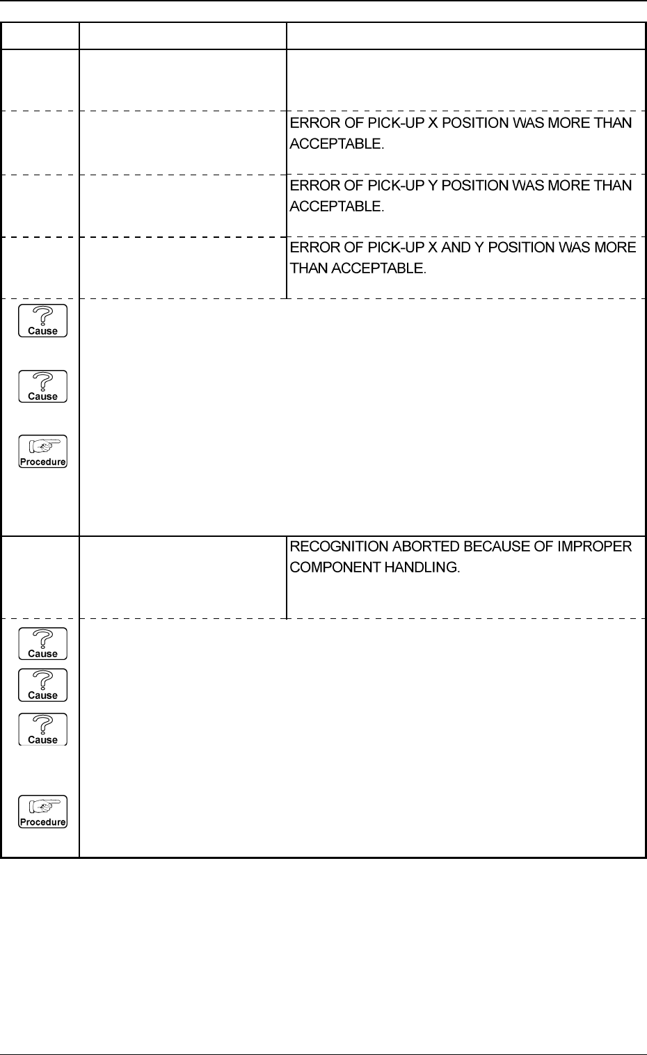
2030X002 PICKED POSTURE ERROR
Note: X represents “1 through
4, 8 and 9”.
5. Component Recognition Error Code and List of Error Messages
0103-003 4-41 Tg0248-PM-ER
Error Code Display A Display B
2030X003 PICKED POSTURE ERROR
Note: X represents “1 through
4, 8 and 9”.
2030X001 PICKED POSTURE ERROR
Note: X represents “1 through
4, 8 and 9”.
ERROR OF PICK-UP ANGLE WAS MORE THAN
ACCEPTABLE.
2030X004 PICKED POSTURE ERROR
Note: X represents “1 through
4, 8 and 9”.
(Cause 1) When a component is picked up, the pick-up positions (X and Y) and angle have
shifted greatly from the correct ones.
(Cause 2) When the tape is fed, a component is turned vertically.
(Reset Procedure in the case of Causes 1 and 2)
Reset Procedure
(1) Check the selected component and the tape feeder.
(2) Check if the feeder (B) offset data is correct.
(3) Check if the component library data is correct.
(4) Check the selected component and the tape feeder.
2031X001 CENTER OF GRAVITY DE-
TECTION ERROR
Note: X represents “1 through
4, 8 and 9”.
(Cause 1) An improper vacuum nozzle is selected for the component or vice versa.
(Cause 2) The component is bent due to weak vacuum suction force.
(Cause 3) When a component is picked up, the pick-up positions (X and Y) and angle have
shifted greatly from the correct ones.
(Reset Procedure in the case of Causes 1, 2 and 3)
Reset Procedure
(1) Check the selected component and vacuum nozzle.
(2) Check the vacuum pressure.