3OM-1064-001.pdf - 第258页
0103-001 4-53-1 Tg0248-PM-ER 5. Component Recognition Error Code and List of Error Messages Error Code Display A Display B 20660003 COMPONENT DETECTION ERROR SOME LEADS CANNOT BE DETECTED. 20660005 COMPONENT DETECTION ER…
0103-003 4-53 Tg0248-PM-ER
5. Component Recognition Error Code and List of Error Messages
Error Code Display A Display B
20630003 COMPONENT DETECTION
ERROR
SOME LEADS CANNOT BE DETECTED.
20630004 COMPONENT DETECTION
ERROR
UNSPECIFIED LEADS ARE DETECTED.
20630005 COMPONENT DETECTION
ERROR
LEAD POSITION WAS OUT OF TOLERANCE.
20630002 COMPONENT DETECTION
ERROR
THE DETECTED LEAD POSITION DOES NOT MATCH
THE POSITION DATA.
20630001 COMPONENT DETECTION
ERROR
COMPONENT NOT FOUND.
20630007 COMPONENT DETECTION
ERROR
RECOGNITION ABORTED BECAUSE OF IMPROPER
COMPONENT HANDLING.
20630006 COMPONENT DETECTION
ERROR
WIDTH OF LEAD EXCEEDS THE TOLERANCE.
20630009 COMPONENT DETECTION
ERROR
CONTRAST BETWEEN COMPONENT AND BACK-
GROUND IS TOO LOW.
20660002 COMPONENT DETECTION
ERROR
UNSPECIFIED LEADS ARE DETECTED.
20630008 COMPONENT DETECTION
ERROR
RECOGNITION ABORTED BECAUSE OF IMPROPER
COMPONENT HANDLING.
(Cause 1) The number of leads is not suitable.
(Cause 2) Objects shaped identically to the leads exist at both ends of the lead group.
(Cause 3) Dirt and dust have accumulated at both ends of the lead group.
(Reset Procedure in the case of Causes 1, 2 and 3)
Reset Procedure
(1) Press the [ZERO] button to return all the axes to their original positions.
(2) Re-start.
(3) If the device can’t be re-started, contact our service personnel.
0103-001 4-53-1 Tg0248-PM-ER
5. Component Recognition Error Code and List of Error Messages
Error Code Display A Display B
20660003 COMPONENT DETECTION
ERROR
SOME LEADS CANNOT BE DETECTED.
20660005 COMPONENT DETECTION
ERROR
LEAD GROUP NOT FOUND.
(Cause 1) The number of leads is not suitable.
(Cause2) The lead width is not suitable.
(Too large or small parameter is set in the "WIDTH" data box of the label "LEAD
DATA".)
(Cause 3) The leads look blurred.
(There is an extremely dark lead compared with other leads.)
(Cause 4) The direction of the component feed (direction of the component) is not suitable.
(Cause 5) Dirt, etc., have adhered to the cover glass in the fixed lighting unit.
(This can be checked through the recognition monitor.)
(Reset Procedure in the case of Causes 1, 2, 3, 4 and 5)
Reset Procedure
(1) Press the [ZERO] button to return all the axes to their original positions.
(2) Re-start.
(3) If the device can’t be re-started, contact our service personnel.
(Cause 1) No component is picked up.
(Cause 2) A different component (small component, etc.) is picked up.
(Cause 3) The lighting is not ON.
(Reset Procedure in the case of Causes 1, 2 and 3)
Reset Procedure
(1) Press the [ZERO] button to return all the axes to their original positions.
(2) Re-start.
(3) If the device can’t be re-started, contact our service personnel.
0103-001 4-53-2 Tg0248-PM-ER
5. Component Recognition Error Code and List of Error Messages
Error Code Display A Display B
20660006 COMPONENT DETECTION
ERROR
LEAD POSITION (LEAD ARRAY DIRECTION) WAS
OUT OF TOLERANCE.
When "AUTO" is set in the "RECOG DATA SET" data box and “MANUAL” in the “RECOG
DATA” data box + "ENBL (AUTO)" in the "LEAD POS (LATL DIR) DETN" data box, the
tolerace is automatically set.
This error can be avoided by setting "MANUAL" in the "RECOG DATA SET" data box and
"DISABLE" in the "LEAD POS (LATL DIR) DETN" data box.
When these parameters are set, no bent lead is detected.
(Cause 1) There is a bent lead.
(Cause 2) The lead width is not suitable.
(When the lead width tolerance is automatically set and a parameter smaller than the
actual width is set as the lead width, a smaller parameter (tolerance decreased as much
as the reduction of the lead width) is also set.)
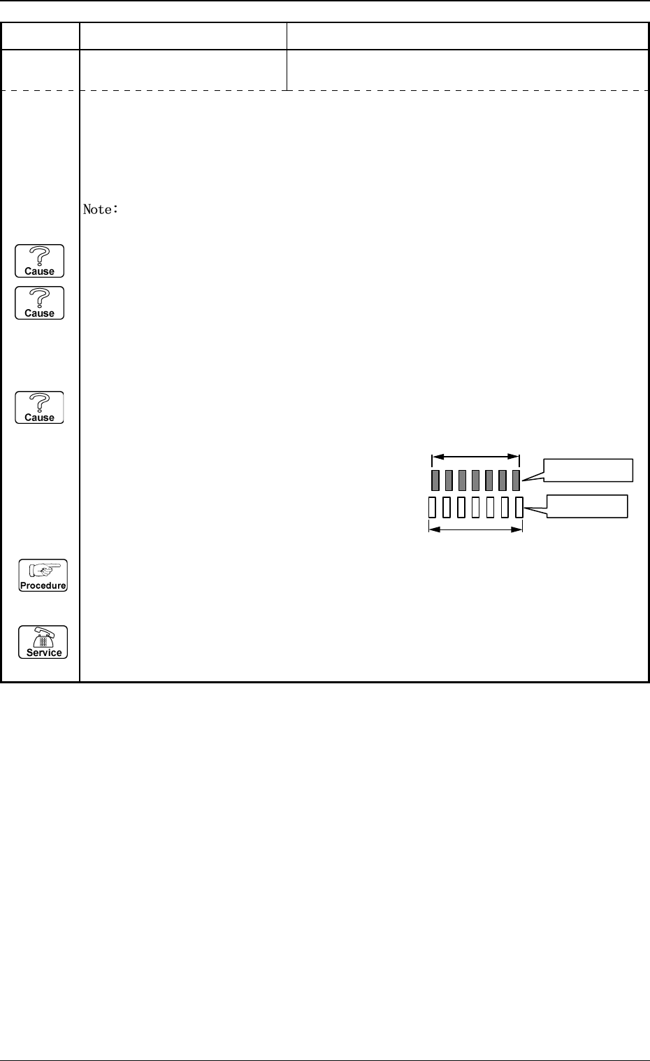
(Cause 3) The component thickness and the camera magnification are not suitable.
(When an image larger or smaller than the actual component size (component data) is
captured, the closer to both ends of the lead
group the leads are located, the greater the
positional deviation becomes and such leads
are detected as "bent ones".)
(Reset Procedure in the case of Causes 1, 2 and 3)
Reset Procedure
(1) Press the [ZERO] button to return all the axes to their original positions.
(2) Re-start.
(3) If the device can’t be re-started, contact our service personnel.
Actual Component
Component Data