3OM-1064-001.pdf - 第27页
1.3 Power Supply 1.3.1 Power Supply Check 1 Symptom The LED of the [POWER ON] button does not illuminate (red or green). Nothing is displayed on the touch screen. Nothing is displayed on the recognition monitor . No soun…

Check whether a problem has arisen in the offset of the P.E.C.
recognition camera. *5
If the offset has a problem, it will result in overall positional devia-
tion of placement.
Confirm that there is no problem in the offset of the P.E.C. recogni-
tion camera.
Note: Although the offset data of the P.E.C. recognition camera can
be taught at the “OFFSET TEACH” display, it is required to
re-teach a series of device offset data. (Hierarchical Sequence:
“SPECIAL SEL.” Display → “OFFSET TEACH” Display)
A special jig is also required for the teaching operations.
Whenever it is necessary to perform the teaching operations,
consult our sales personnel for details.
0005-002 1-18 Tg0248-PM-ER
1. Cause and Remedy of Simple Trouble
1.3 Power Supply
1.3.1 Power Supply Check 1
Symptom
The LED of the [POWER ON] button does not illuminate (red or green).
Nothing is displayed on the touch screen.
Nothing is displayed on the recognition monitor.
No sound (operating sound) is produced from the electromagnetic contactor.
........... etc.
0005-002 1-19 Tg0248-PM-ER
1. Cause and Remedy of Simple Trouble
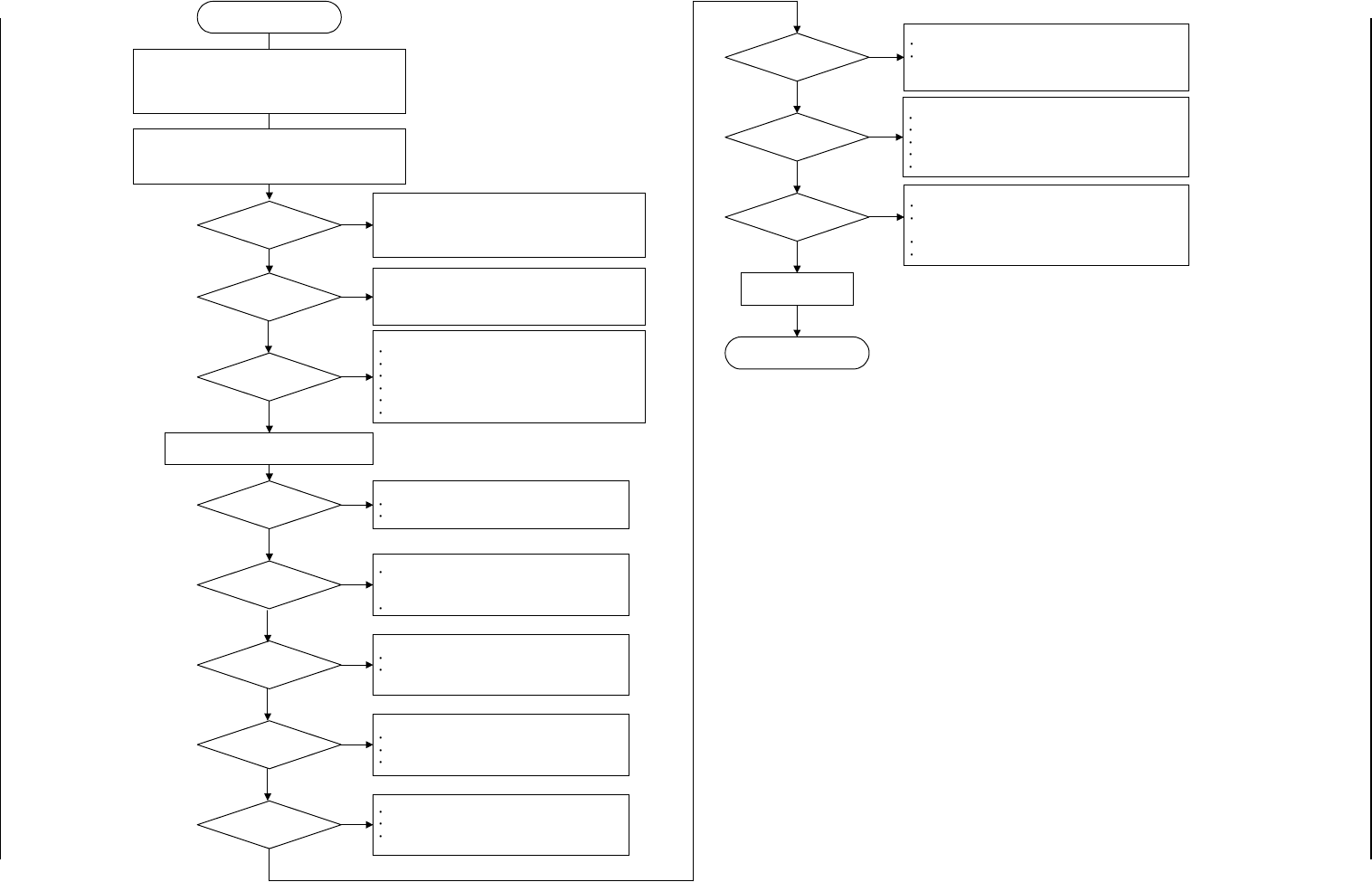
When the [POWER ON]
button is pressed, power is
not supplied.
Is the power breaker
"ON"?
YES
Turn on the power
breaker .
Is the main power lamp
"ON"?
Is the [POWER OFF]
button kept pressed?
YES
Did you press the
[POWER ON] button for
a few seconds?
Is the LCD touch
screen powered?
Is the recognition
monitor powered?
Did the initialization
display appear on the
LCD touch screen?
Perform the operation check on Control DC Power
Supply Units G01, G02, and G03.
The control board may be in abnormal condition.
Check how the connector is connected.
Replace the control board with a new one.
YES
YES
YES
YES
YES
Press the [POWER ON]
button for approximately 2
seconds to re-supply power
to the machine.
[Release the
[POWER OFF]
button.
NO
NO
Check whether the switch on the rear side of the LCD touch
screen is turned "ON".
Check whether the circuit protector of the LCD touch screen is
tripped.
Check whether Fuse F111 or F112 has melted, breaking the
circuit.
Check each component and wiring.
When the power switch of the monitor is "OFF", turn it "ON".
Note:
When "K08" is "ON", the check monitor will not be
powered.
Check whether Fuse F113 has melted, breaking the circuit.
Check each component and wiring.
Confirm that no 3.5-inch floppy disk is inserted in the floppy disk
drive.
Perform the operation check on Control DC Power Supply Units
G01, G02, and G03.
The control board may be in abnormal condition.
Check how the connector is connected.
Replace the control board with a new one.
NO
NO
NO
To "1.3.2 Power Supply
Check 2"
Components and wiring
must be checked.
!!High Voltage!!
Avoid any electric shock.
Electrical knowledge is required. Only a
service personnel or an authorized
personnel should perform this operation.
NO
Is the power (200 V AC,
3-Phase) normal?
Open the power breaker box and check
the inside electrically.
Turn off the power breaker crank.
Remove the screw located on the bottom
of the power breaker box and open the
door of the power breaker box.
Has Fuse F201, 202, or
203 melted, breaking the
circuit?
!!High Voltage!!
Turn on the power breaker.
Check the components and wiring.
Perform operation check on DC
Power Supply (G06) and 24 V DC
(24D).
Open the cover located at the lower
part of the front side and check 24 V
DC (24D) at the terminal.
Check the wiring.
Turn off the power breaker crank,
remove the screw located at the bottom
of power breaker box, and check the
fuses.
When a fuse has melted, replace it with
a new one.
Check whether the factory-equipped
breaker is tripped.
Check whether the local power is
normal.
Check whether the power cable to the
machine is normal.
NO
YES
YES
YES
NO
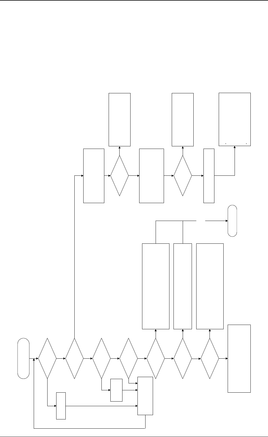
1.3.2 Power Supply Check 2
Symptom
Although the main power lamp is “ON”, power is not supplied.
0005-002 1-20 Tg0248-PM-ER
1. Cause and Remedy of Simple Trouble
Although the main power lamp
is "ON", power is not supplied.
Is the breaker at the
power supply section
tripped?
Did the timer (KT01) and
the electromagnetic
contactor (KM01) turn
"ON"?
Are the cooling fans
(located on the sides and
ceiling of the main body)
working?
!!High Voltage!!
Avoid any electric shock.
Electrical knowledge is required. Only a service personnel
or an authorized personnel should perform this operation.
YES
YES
YES
Check the following items.
Breakers (Q204, Q101)
Transformers
Wiring (X1, X2, and Y1) in 100 V AC System
Contacts of Electromagnetic Contactor (KM01)
Fuses (F105, 106, 109, 110)
Connectors
Check the following items.
24 V DC Power Supply (G08)
Fuse (F003)
24 V DC or not in 24F1 and 10F
NO
Check the following items.
24 V DC Power Supply (G06) in Control Box
24 V DC or not in 24C and 10C
When this 24 V DC is not normal, the SDS I/O does not
work.
Check the following items.
Relay (ON or OFF) in Control Box
24 V DC or not in 24C and 10C
Connector (XCN3) of Relay Board in Control Box
Operation of I/O Board
Connector (XCN93) on Rear Side of Control Box
NO
YES
NO
Open the front cover of the control box and
check the DC power supply (G01).
!!High Voltage!!
Open the cover located at the lower part of the front left
side of the machine.
Turn on the power breaker.
Are the cooling fans
(located on the sides and
ceiling of the main body)
working?
Is the DC power supply
(G01) in the control box
working?
YES
Is an alarm issued from
the control board?
Is the control power 24 V
DC (G08) in abnormal
condition?
(24F1 and 10F)
Is the control power 24 V
DC (G07) in abnormal
condition?
(24E and 10E)
NO
NO
NO
NO
Check the following items.
24 V DC Power Supply (G07)
Fuses (F001 and F002)
24 V DC or not in 24E1, 24E2, and 10E
Check the following items.
Wiring in 100 V AC System, Contacts of
Electromagnetic Contactor (KM01), and Connectors
(X1, X2, and Y1)
Breaker (W203)
Check the following items.
Indicator Lamps of Boards
Power Voltage (5 V DC, 12 V, -12 V) of Control
Board Rack
Check the following items.
Fuses (F121, 122, 123, 124, 125)
Connectors
When a breaker (Q203, Q204, or Q101) is tripped, the
control power cannot be supplied.
When a breaker is tripped, confirm that no abnormality is
found on the loaded side of the breaker and turn on the
power breaker crank again.
Press the [POWER ON] button and check whether the timer
(KT01) turns "ON".
Check the coil voltage of the electromagnetic contactor (KM01).
(24 V DC or not in 502, 503, 504, and 10D)
Check the wiring.
NO
NO
NO
Is 24 V DC (G06) for
SDS in normal condition?
(24C and 10C)
Is the relay (K09)
working?
Is the relay (K50) in
Power 2 Section
working?
To "1.3.3 Power Supply for
Main Loads"
Operation Check on
Each Component
YES
YES
YES
YES
YES
YES
Check the following items.
Operation of I/O Board
Operation of Mechanical Distribution Board (Mechanical
Distribution 1) in Power Supply 2 Section
Relay K50
Connectors
NO