3OM-1064-001.pdf - 第276页
0103-003 4-55 Tg0248-PM-ER 5. Component Recognition Error Code and List of Error Messages Error Code Display A Display B 20672142 COMPONENT DETECTION ERROR UNSPECIFIED LEADS ARE DETECTED. 20672141 COMPONENT DETECTION ERR…
0103-001 4-54-8 Tg0248-PM-ER
5. Component Recognition Error Code and List of Error Messages
Error Code Display A Display B
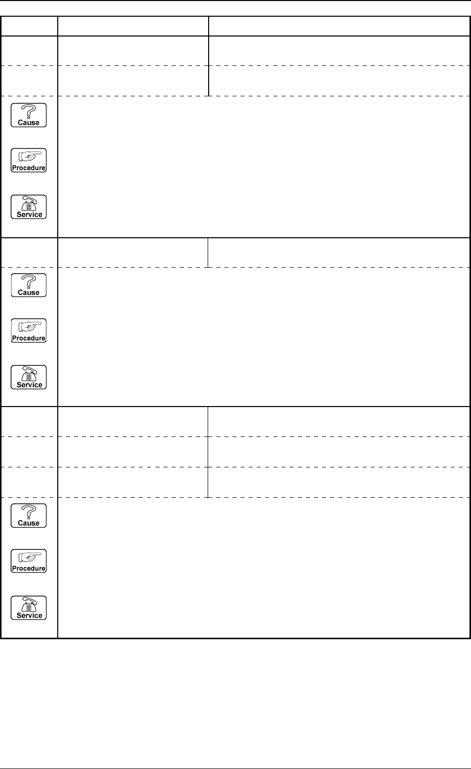
20672124 COMPONENT DETECTION
ERROR
PART OF COMPONENT OUTLINE IS OUT OF VISUAL
FIELD FOR RECOGNITION.
20672123 COMPONENT DETECTION
ERROR
OUTLINE OF COMPONENT NOT FOUND.
20672125 COMPONENT DETECTION
ERROR
COMPONENT OUTLINE NOT FOUND.
20672126 COMPONENT DETECTION
ERROR
THE COMPONENT OUTLINE DOES NOT MATCH THE
CORRESPONDING DATA.
20672128 COMPONENT DETECTION
ERROR
POSITIONING ABORTED BECAUSE OF IMPROPER
COMPONENT HANDLING.
20672127 COMPONENT DETECTION
ERROR
THE CONTOUR OF COMPONENT DOES NOT MATCH
THE CORRESPONDING DATA.
(Cause 1) This is the device’s self-diagnostic message.
(Reset Procedure in the case of Cause 1)
Reset Procedure
(1) Press the [ZERO] button to return all the axes to their original positions.
(2) Re-start.
(3) If the device can’t be re-started, contact our service personnel.
(Cause 1) Improper parameters are set in the "X" and "Y" data boxes of the label "MOLD SIZE".
(Reset Procedure in the case of Cause 1)
Reset Procedure
(1) Press the [ZERO] button to return all the axes to their original positions.
(2) Re-start.
(3) If the device can’t be re-started, contact our service personnel.
(Cause 1) This is the device’s self-diagnostic message.
(Reset Procedure in the case of Cause 1)
Reset Procedure
(1) Press the [ZERO] button to return all the axes to their original positions.
(2) Re-start.
(3) If the device can’t be re-started, contact our service personnel.
0103-003 4-55 Tg0248-PM-ER
5. Component Recognition Error Code and List of Error Messages
Error Code Display A Display B
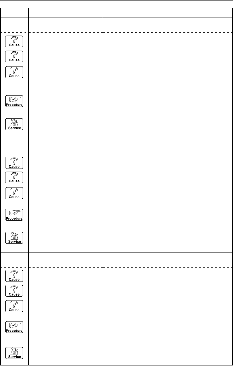
20672142 COMPONENT DETECTION
ERROR
UNSPECIFIED LEADS ARE DETECTED.
20672141 COMPONENT DETECTION
ERROR
LEAD NOT FOUND.
20672129 COMPONENT DETECTION
ERROR
THE OUTLINE CANNOT BE DETECTED AD-
EQUATELY.
(Cause 1) Improper parameters are set in the "X" and "Y" data boxes of the label "MOLD SIZE".
(Cause 2) The diameter of the selected nozzle is larger than the outline of the component.
(Cause 3) Improper parameters are set in the "X" and "Y" data boxes of the label "NOZZLE
OUTER SIZE" at the "NOZZLE TYPE DATA" display.
(Reset Procedure in the case of Causes 1, 2 and 3)
Reset Procedure
(1) Press the [ZERO] button to return all the axes to their original positions.
(2) Re-start.
(3) If the device can’t be re-started, contact our service personnel.
(Cause 1) No component is picked up.
(Cause 2) A different component (small component, etc.) is picked up.
(Cause 3) The lighting is not ON.
(Reset Procedure in the case of Causes 1, 2 and 3)
Reset Procedure
(1) Press the [ZERO] button to return all the axes to their original positions.
(2) Re-start.
(3) If the device can’t be re-started, contact our service personnel.
(Cause 1) The number of leads is not suitable.
(Cause 2) Objects shaped identically to the leads exist at both ends of the lead group.
(Cause 3) Dirt and dust have accumulated at both ends of the lead group.
(Reset Procedure in the case of Causes 1, 2 and 3)
Reset Procedure
(1) Press the [ZERO] button to return all the axes to their original positions.
(2) Re-start.
(3) If the device can’t be re-started, contact our service personnel.
0103-001 4-55-1 Tg0248-PM-ER
5. Component Recognition Error Code and List of Error Messages
Error Code Display A Display B
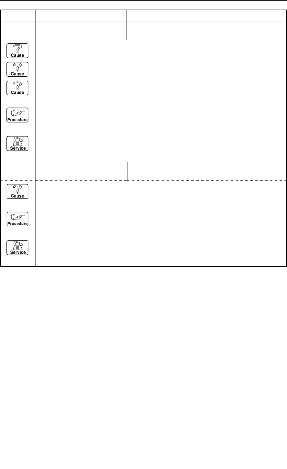
20672144 COMPONENT DETECTION
ERROR
LEAD GROUP NOT FOUND.
20672145 COMPONENT DETECTION
ERROR
THE LEAD AT THE END OF LEAD GROUP CANNOT
BE DETECTED.
(Cause 1) No component is picked up.
(Cause 2) A different component (small component, etc.) is picked up.
(Cause 3) The lighting is not ON.
(Reset Procedure in the case of Causes 1, 2 and 3)
Reset Procedure
(1) Press the [ZERO] button to return all the axes to their original positions.
(2) Re-start.
(3) If the device can’t be re-started, contact our service personnel.
(Cause 1) This is the device’s self-diagnostic message.
(Reset Procedure in the case of Cause 1)
Reset Procedure
(1) Press the [ZERO] button to return all the axes to their original positions.
(2) Re-start.
(3) If the device can’t be re-started, contact our service personnel.