3OM-1064-001.pdf - 第278页
0103-001 4-55-2 Tg0248-PM-ER 5. Component Recognition Error Code and List of Error Messages Error Code Display A Display B 20672147 COMPONENT DETECTION ERROR LEAD POSITION (LEAD LENGTH DIRECTION) W AS OUT OF TOLERANCE. 2…
0103-001 4-55-1 Tg0248-PM-ER
5. Component Recognition Error Code and List of Error Messages
Error Code Display A Display B
20672144 COMPONENT DETECTION
ERROR
LEAD GROUP NOT FOUND.
20672145 COMPONENT DETECTION
ERROR
THE LEAD AT THE END OF LEAD GROUP CANNOT
BE DETECTED.
(Cause 1) No component is picked up.
(Cause 2) A different component (small component, etc.) is picked up.
(Cause 3) The lighting is not ON.
(Reset Procedure in the case of Causes 1, 2 and 3)
Reset Procedure
(1) Press the [ZERO] button to return all the axes to their original positions.
(2) Re-start.
(3) If the device can’t be re-started, contact our service personnel.
(Cause 1) This is the device’s self-diagnostic message.
(Reset Procedure in the case of Cause 1)
Reset Procedure
(1) Press the [ZERO] button to return all the axes to their original positions.
(2) Re-start.
(3) If the device can’t be re-started, contact our service personnel.
0103-001 4-55-2 Tg0248-PM-ER
5. Component Recognition Error Code and List of Error Messages
Error Code Display A Display B
20672147 COMPONENT DETECTION
ERROR
LEAD POSITION (LEAD LENGTH DIRECTION) WAS
OUT OF TOLERANCE.
20672146 COMPONENT DETECTION
ERROR
LEAD NOT FOUND.
(Cause 1) The number of leads is not suitable.
(Cause 2) The lead width is not suitable.
(Too large or small parameter is set in the "WIDTH" data box of the label "LEAD
DATA".)
(Cause 3) The leads look blurred.
(There is an extremely dark lead compared with other leads.)
(Cause 4) The direction of the component feed (direction of the component) is not suitable.
(Cause 5) Dirt, etc., have adhered to the cover glass in the fixed lighting unit.
(This can be checked through the recognition monitor.)
(Reset Procedure in the case of Causes 1, 2, 3, 4 and 5)
Reset Procedure
(1) Press the [ZERO] button to return all the axes to their original positions.
(2) Re-start.
(3) If the device can’t be re-started, contact our service personnel.
This error occurs when "MANUAL" is set in the "RECOG DATA SET" data box, "ENBL
(AUTO)" or "ENBL (MNL)" in the "LEAD POS (LONG DIR) DETN" data box, and the longitu-
dinal direction of the lead exceeds its tolerance.
When "ENBL (AUTO)" is set in the "LEAD POS (LONG DIR) DETN" data box, the tolerance is
automatically set.
(Cause 1) The lead end is longer than the component data or a shorter lead exists.
(Cause 2) The leads look blurred.
(There is an extremely dark lead compared with other leads.)
(Reset Procedure in the case of Causes 1 and 2)
Reset Procedure
(1) Press the [ZERO] button to return all the axes to their original positions.
(2) Re-start.
(3) If the device can’t be re-started, contact our service personnel.
0103-001 4-55-3 Tg0248-PM-ER
5. Component Recognition Error Code and List of Error Messages
Error Code Display A Display B
20672148 COMPONENT DETECTION
ERROR
LEAD POSITION (LEAD ARRAY DIRECTION) WAS
OUT OF TOLERANCE.
When "AUTO" is set in the "RECOG DATA SET" data box and in the "RECOG DATA" data box
+ "ENBL (AUTO)" in the "LEAD POS (LATL DIR) DETN" data box, The tolerance is automati-
cally set.
This error can be avoided by setting in the "RECOG DATA" data box + in the "RECOG DATA
SET" data box and "DISABLE" in the "LEAD POS (LATL DIR) DETN" data box.
When these parameters are set, no bent lead is detected.
(Cause 1) There is a bent lead.
(Cause 2) The lead width is not suitable.
(When the lead width tolerance is automatically set and a parameter smaller than the
actual width is set as the lead width, a smaller parameter (tolerance decreased as much
as the reduction of the lead width) is also set.)
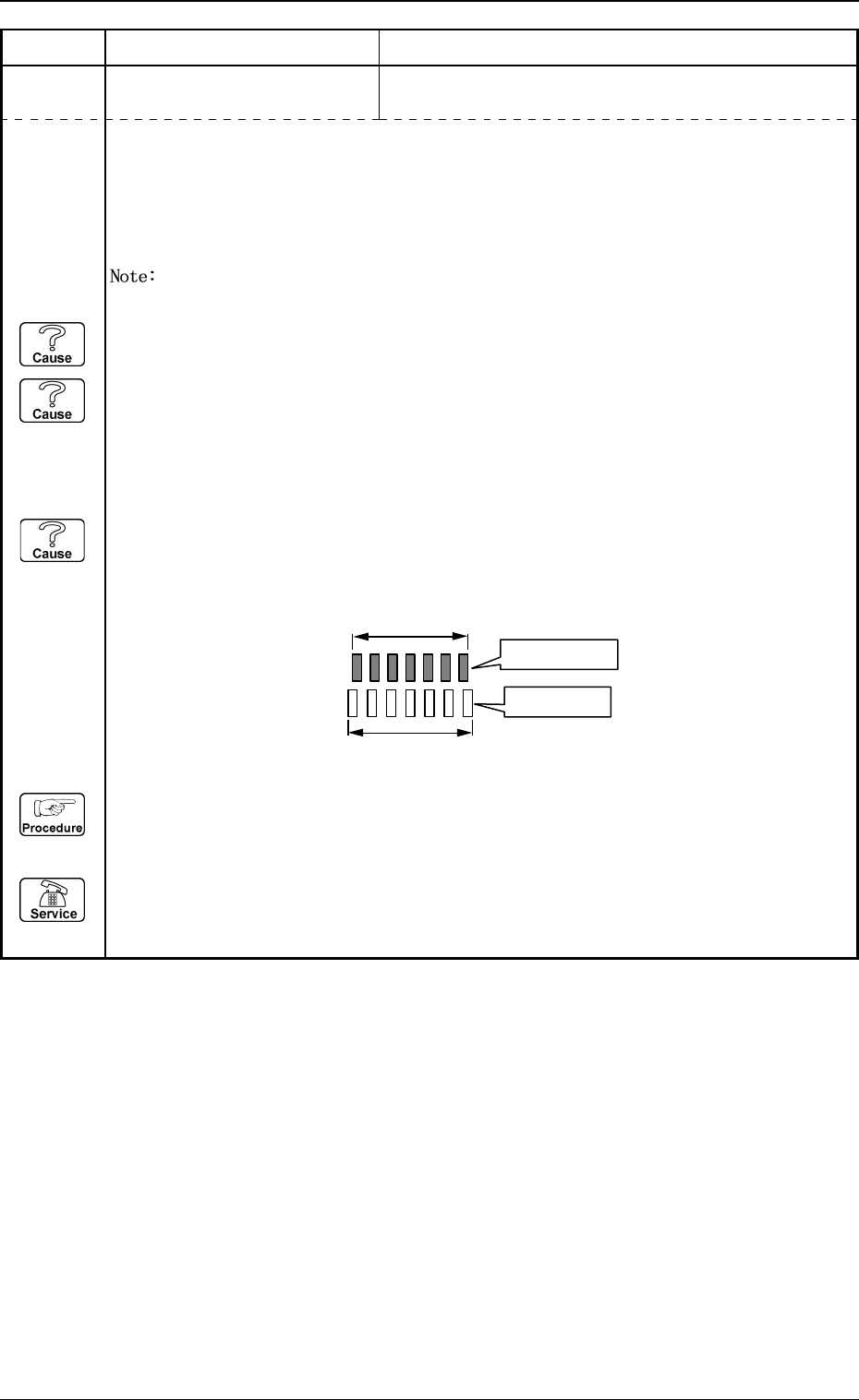
(Cause 3) The component thickness and the camera magnification are not suitable.
(When an image larger or smaller than the actual component size (component data) is
captured, the closer to both ends of the lead group the leads are located, the greater the
positional deviation becomes and such leads are detected as "bent ones".)
(Reset Procedure in the case of Causes 1, 2 and 3)
Reset Procedure
(1) Press the [ZERO] button to return all the axes to their original positions.
(2) Re-start.
(3) If the device can’t be re-started, contact our service personnel.
Actual Component
Component Data