3OM-1064-001.pdf - 第30页
1.3.4 Servo Power Supply Symptom Beam A or B is not powered. The servo power lamp on the rear or the front side does not illuminate. No sound (operating sound) is produced from the electromagnetic contactor . ...........…
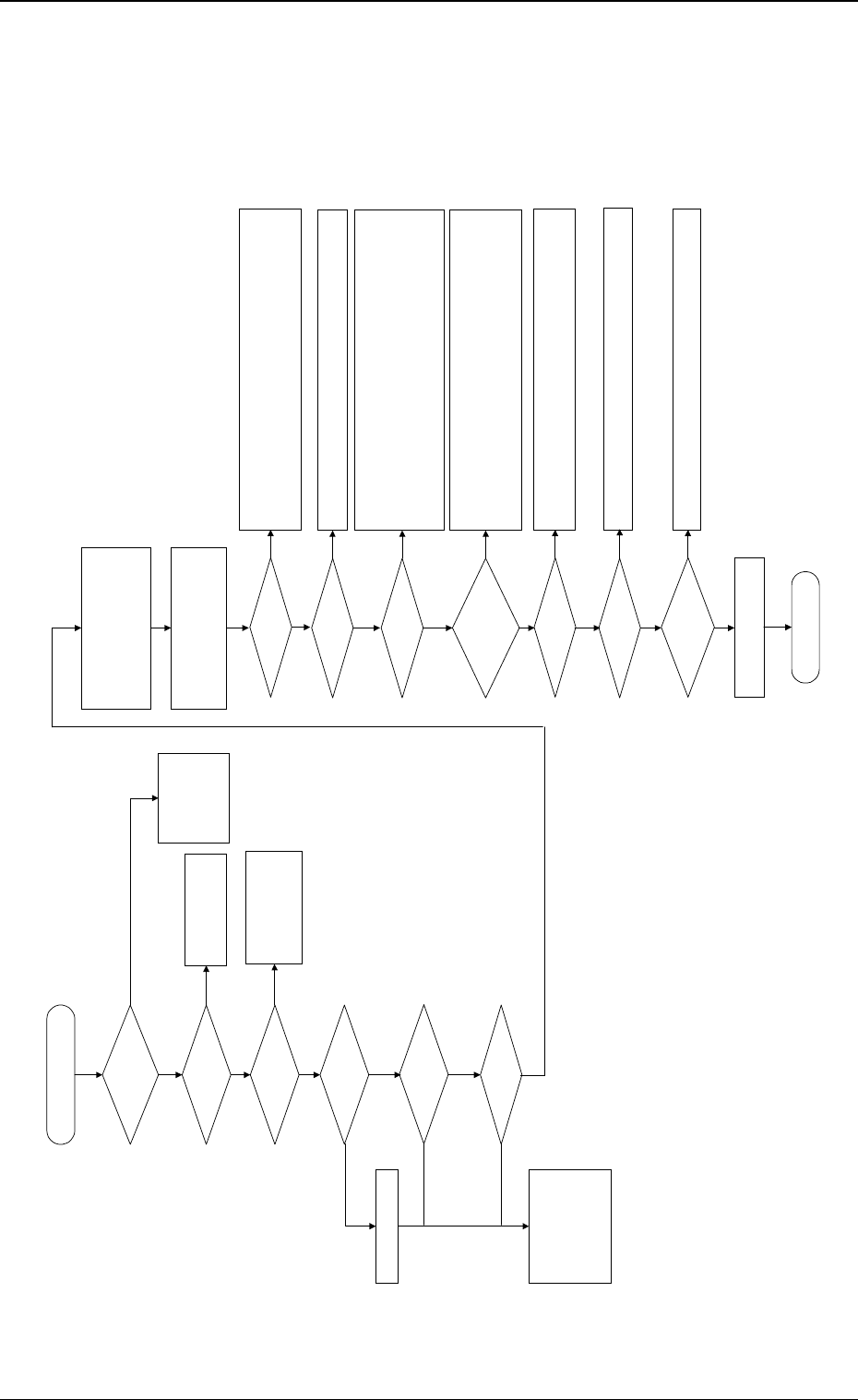
1.3.3 Power Supply for Main Loads
Symptom
The [POWER ON] button does not illuminate green.
No sound (operating sound) is produced from the electromagnetic contactor.
........... etc.
0005-002 1-21 Tg0248-PM-ER
1. Cause and Remedy of Simple Trouble
The power supply (main) for
loads is not supplied.
Is the LED of the [POWER
ON] button "ON" in green?
Is the air pressure normal?
Adjust the air pressure.
Check whether Q101, Q203, Q204, Q205, Q111, or Q351A are tripped.
If tripped, confirm that no abnormality is found on the loaded side and then tur
n
on the power breaker crank again.
Check whether Relays K02, K04, and K05 are working.
Is the maintenance cover
(supply cover) closed?
When the switch is "ON", turn it off.
Confirm that Relays K63, 64, 65, 66, 67, and 68 are "OFF".
When a relay is "ON" although the switch is "OFF", abnormality will be found i
n
the wiring. Check the wiring.
When this switch is "ON", the initial startup operation cannot be executed.
Check whether each load is
working.
Check the supply cover and the [EMERGENCY STOP] buttons.
Check the wiring and connectors.
To "1.3.4 Servo Power
Supply"
Is the LED of the [POWER
ON] button "ON" in red?
The load power
supply circuit is
normal.
Check whether each
component and
wiring are normal.
Is a display on the
operation monitor (touch
screen)?
Check how the control
board works.
Check the power supply
system of the control
board.
Is the [EMERGENCY
STOP] button pressed?
There is a possibility that the sensor is not working normally.
Check the sensor and the wiring.
Check how the interlock board is working.
Is the relay (K51)
turned "ON"?
ޓޓޓޓ
!!High Voltage!!
Avoid any electric shock.
Electrical knowledge is required. Only a
service personnel or an authorized
personnel should perform this
operation.
Are the electromagnetic
contactors (KM08, 09,
112A, and 112B) "ON"?
ޓޓޓޓ
!!High Voltage!!
Open the cover located at the lower
part of the front left side of the
machine.
Turn on the power breaker crank.
YES
YES
NO
NO
NO
YES
YES
YES
YES
NO
YES
NO
Check the air pressure,
release the [EMERGENCY
STOP] button, reset the
maintenance cover, and
press the [POWER ON]
button for approximately 2
seconds to re-supply
power.
Check the wiring.
24 V DC (Check the 24D1
line.)
Is the circuit breaker
tripped?
Are the relays (K60, 61, and
62) working?
YES
NO
NO
Is the safety relay (K99)
working?
Are the interlock bypass
switches and [OPERATION
MODE] buttons (both front
and rear ones) turned
"OFF"?
YES
NO
NO
Are the electromagnetic
contactors (KM103A, 104A,
115A, 103B, and 104B)
"ON"?
Check the electromagnetic contactors and the wiring.
Check the electromagnetic contactors and the wiring.
Check the fuses built in the relays.
Confirm that the electromagnetic contactors (KM08, 09, KM112A, 103A, 104A,
151A, 112B, 103B, 104B) are "OFF".
Check for welded contacts.
Confirm that 24 V DC is supplied between Terminals X2 and T21 when Timer
KT01 is working.
Confirm that 24 V DC is supplied between Terminals T12 and T21 and betwee
n
Terminals B1 and T22.
NO
NO
NO
YES
YES
NO
YES
YES
YES
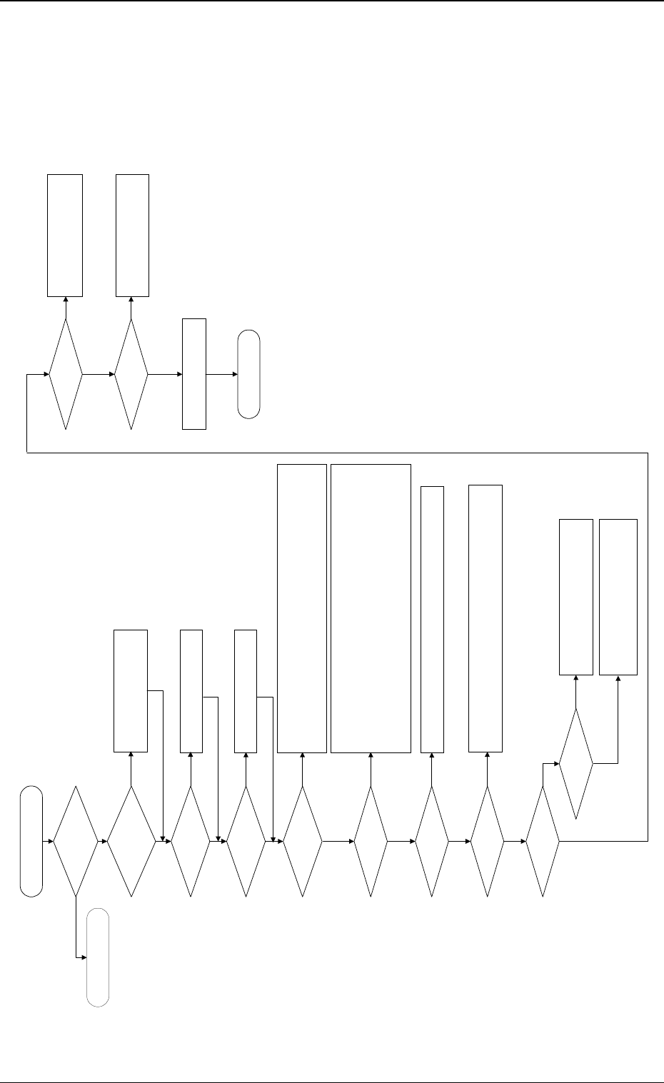
1.3.4 Servo Power Supply
Symptom
Beam A or B is not powered.
The servo power lamp on the rear or the front side does not illuminate.
No sound (operating sound) is produced from the electromagnetic contactor.
............ etc.
0005-002 1-22 Tg0248-PM-ER
1. Cause and Remedy of Simple Trouble
Check the power supply for the X/
Y axis of Beams A and B.
Is the power for loads
supplied?
Is the LED of the [POWER
ON] button "ON" in green?
Are the [READY] button on
the rear side pressed and
the material supply door
locked?
Set the [OPERATION/SET UP]
switches on both front and rear sides
back to the "OPERATION" side.
Check whether neither Q311A, 301A, 302A, 303A, 304A nor Q311B, 301B, 302B, 303B,
304B is tripped.
If tripped, confirm that no abnormality is found on the loaded side and then turn on the
power breaker crank again.
Check whether the relays (K101A/101B) are working.
Are the safety relays
(K131A/K131B) working?
Check whether the fuses (K051A/K051B) have melted, breaking the circuits.
Confirm that the electromagnetic contactors (KM111A, 1113A, 1114A, 101A, 102A/
KM111B, 1113B, 1114B, 101B, 102B) are "OFF".
Confirm that no contacts have been welded.
Confirm that Relay K65 is "OFF".
Confirm that Relays K61, K62, K123A, and 124A/K123B, and 124B are "ON".
Confirm that Relays K115A/K115B are "ON".
Confirm that Relay K122A is "ON". (Confirm that the Y-axis mechanical stopper has
returned.)
Check whether each load is
normal.
Is an alarm produced from
the servo driver?
Check the contents of the alarm.
Check the servomotor driver and motor wiring.
Check how the relays (K102A, 103A/K102B,
103B) are working.
Check the wiring.
Check the SDS output node.
END
To "1.3.3 Power Supply for
Main Loads"
Is the [OPERATION/SET
UP] switch set to the
"OPERATION" side?
(Both Front and Rear Sides)
Press the [READY] button to lock the
material supply door.
Are the supply and
maintenance cover closed?
Close the supply and maintenance
cover.
Is the circuit breaker
tripped?
Is the electromagnetic
contactor "ON"?
Check how the electromagnetic contactors (KM111A, 1113A, 114A/KM111B,
1113B, 1114B) are working.
Check the wiring.
Are the relays (K102A,
103A/K102B, 103B) "ON"?
Check the sensor.
Check the interlock board.
Check the wiring.
Are the relays (K111A/
K111B) "ON"?
Is the electromagnetic
contactor "ON"?
Check how the electromagnetic
contactors (KM101A, 102A/KM101B,
102B) are working.
Check the wiring.
Are the servo power lamps
(HD51A/HD51B) "ON"?
Check the lamps.
Check the wiring.
YES
YES
NO
NO
NO
NO
YES
YES
NO
YES
NO
YES
YES
NO
NO
YES
NO
NO
YES
YES
NO
YES
NO
YES
YES
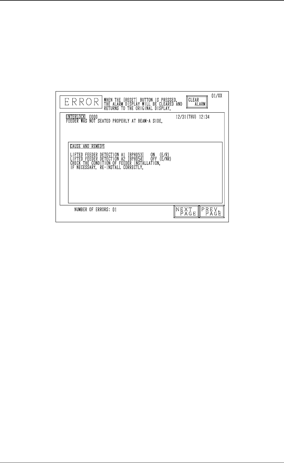
2. Cause and Remedy of Tape Feeder Installation
Error (Lifted Feeder)
Whenever a feeder installation error (lifted feeder) is detected, the machine
stops instantaneously in an error condition and an error message is issued re-
gardless of machine operation mode (“RUN”, “PAUSE”, or “STOP”) except
for the time when a feeder is replaced with the supply cover being opened
because machine protection has top priority.
Fig. 1.1
Cause of Feeder Installation Error (Lifted Feeder)
• The tape feeder is not seated correctly.
• The suppressor of the tape feeder is disengaged and kept afloat (lifted).
• A component has popped out from the tape feeder or the vibratory stick
feeder and is shielding the lifted feeder detection sensor.
• A vertical component is picked up because the pick-up position has deviated
from the correct one or the tape is not fed normally and the picked compo-
nent is shielding the sensor at the position where the head has ascended.
• The foreign substance was detected.
• The amount of slack of the tape is large.
Remedy
(1) Press the [RESET] button to cancel the error condition.
(2) Press the [READY] button on the side where the lifted feeder was de-
tected to unlock the supply cover.
(3) Open the supply cover and remove the cause of the lifted feeder detec-
tion.
(4) Confirm that the light is emitted and received by the lifted feeder detec-
tion sensor.
(Confirm that the indicator lamp of the sensor is “ON”.)
(5) Close the supply cover and press the [READY] button to lock the cover.
(6) Press the [ZERO] button to zero each device.
(7) After all devices are zeroed completely, press the [START] button to re-
start the operation.
0005-002 1-23 Tg0248-PM-ER
2. Cause and Remedy of Tape Feeder Installation Error (Lifted Feeder)