YSi-X_Ope_E.pdf - 第102页
4-41 4 Maintenance 8.2 Replacing the UPS (uninterr uptible power supply) batter y T he UPS battery used in this equipment will wear down, reaching the end of its service life. The battery service life and replacement int…
4-40
4
Maintenance
5
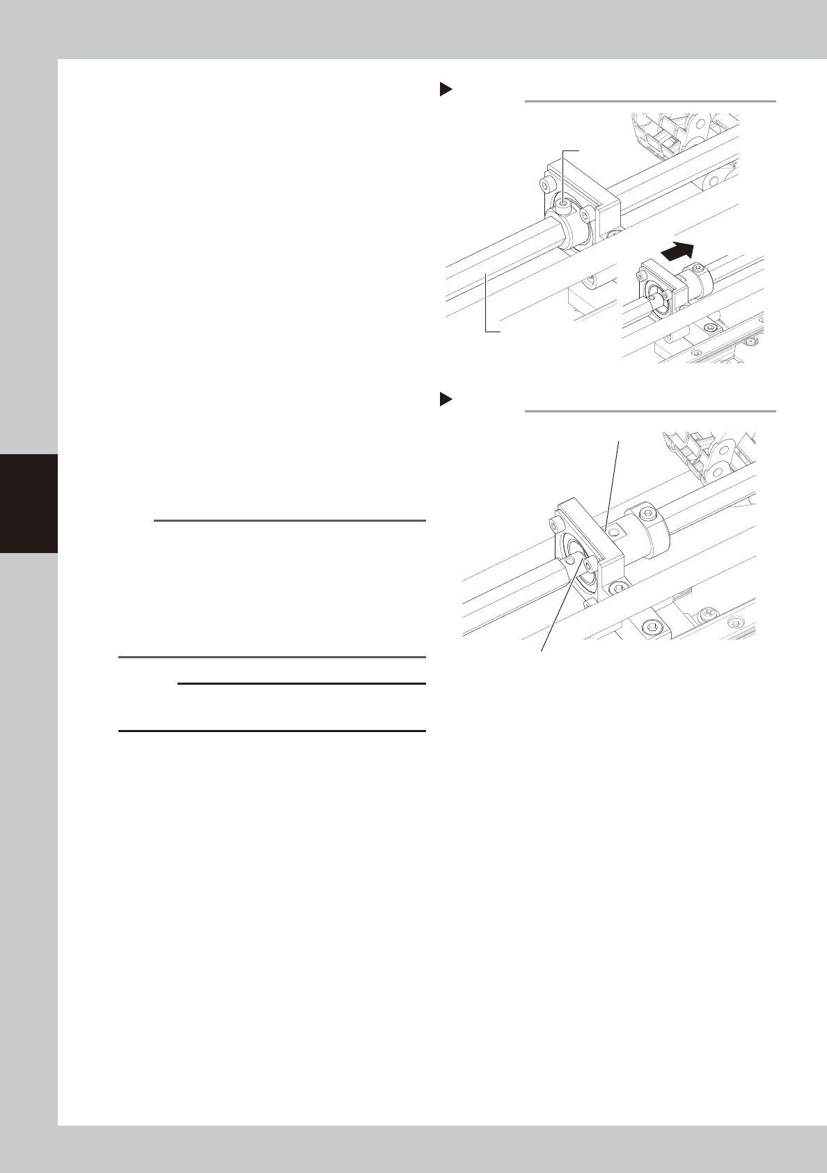
Separate the hexagonal shafts.
Loosen the clamp bolt on the shaft coupling
with the hex wrench (3) and move the rear
hexagonal shaft to rearward together with
the coupling.
53453-M6-00
6
Detach the belt from the conveyor.
Take the belt out through the gap between
the separated hexagonal shafts. After
detaching the belt, use the fine brush or
paper wipe to clean the clearance between
the conveyor frame and board guide.
53454-M6-00
7
Attach a new belt.
1. Temporarily fit a new belt onto the pulley.
2. Reconnect the rear hexagonal shaft to
the coupling and tighten the clamp bolt
on the coupling with the hex wrench (3).
3. Tighten the drive pulleys at both ends
with the hex wrenches (4 and 5).
4. Tighten the tension pulley while applying
a proper tension to the belt by moving
the tensioner pulley.
TIP
Proper belt tension and pulley pitch are as follows:
•
When a tension gauge is used
Tension 190 to 160Hz
Pulley pitch 128mm
•
When no tension gauge is used
Pulley pitch 35 to 38mm
See the next section 5.4, “Checking the conveyor belt
tension”, for more details.
c
CAUTION
The tightening torque for the tension pulley must be set
to 5.5N·m.
8
Check the belt condition.
1. Turn the hexagonal spline shaft by hand
to rotate the belt and check if the belt
rotates smoothly with no slack.
If there is a large slack in the belt, adjust
the tension pulley position.
2. Close the front safety door of the
machine, release the emergency stop
button, and press the [READY] button.
3. On the [Unit]-[Conveyor] tab, press the [L.
Conv.] or [R. Conv.] button to rotate the
belt.
e
4. Press the emergency stop button, open
the front safety door of the machine,
and check the belt condition. If there is
no problem, the adjustment is complete.
Detaching the belts
Step 6
Detach the front belt through this gap.
Detach the rear belt through this gap.
Separating the hexagonal shafts
Step 5
Hexagonal shaft
Clamp bolt

4-41
4
Maintenance
8.2 Replacing the UPS (uninterruptible power supply) battery
The UPS battery used in this equipment will wear down, reaching the end of its service life. The battery service
life and replacement interval differ depending on the usage environment (ambient temperature, etc.).
For detailed information on how to replace the UPS battery, see the user's manual that comes with the UPS.
n
NOTE
When you have replaced the UPS battery, write the replacement date on the label affixed to the UPS unit and the left
side of the main switch.

Chapter 5 Lubrication points
Contents
1.
Lubrication points and applicable grease
5-1
1.1 Applicable grease 5-1
1.2 Grease gun 5-1
2. Lubrication of each unit 5-2
2.1 Each axis unit 5-2
2.1.1 XT and YT-axis guide and ball screw 5-2
2.1.2 LX-axis guide and ball screw 5-3
2.1.3 LY-axis guide and ball screw 5-4
2.1.4 W-axis guide and ball screw 5-5
2.1.5 MS-axis guide 5-6
2.1.6 HZ and HS-axis guide and ball screw 5-7