YSi-X_Ope_E.pdf - 第111页
Contents 1. Power connection terminals A-1 2. Connection between machines A-2 3. UPS (Uninterruptible Power Supply) A-3 3.1 Safety precaution A-3 3.1.1 Precautions when shipping or exporting the UPS A-3 3.1.2 Disposing o…
5-7
5
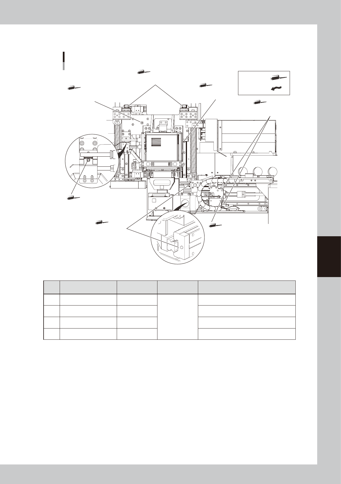
Lubrication points
2.1.6 HZ and HS-axis guide and ball screw
Lubrication points on HZ and HS axes
1. HZ axis guide
Grease nipple
1. HZ axis guide
Grease nipple
3. HS axis guide
Grease nipple
3. HS axis guide
Grease nipple
1. HZ axis guide
Grease nipple
2. HZ axis ball screw
Grease nipple
4. HS axis ball screw
Grease nipple
Grease gun:
Apply by hand:
53507-M6-00
Unit to be lubricated
Lubrication
point
Interval Lubrication method
1 HZ-axis guide 4
Once every
6 months
Grease gun with standard nozzle
2 HZ-axis ball screw 1 Grease gun with standard nozzle
3 HS-axis guide 4 Grease gun with standard nozzle
4 HS-axis ball screw 1 Grease gun with standard nozzle

Contents
1. Power connection terminals A-1
2. Connection between machines A-2
3. UPS (Uninterruptible Power Supply) A-3
3.1 Safety precaution A-3
3.1.1 Precautions when shipping or exporting the UPS A-3
3.1.2 Disposing of used battery after replacement A-3
3.1.3 Safety precautions A-3
3.2 About the UPS A-5
3.3 Operation and setting A-6
3.3.1 Front panel A-6
3.3.2 Operation during normal operation (power is normal) A-6
3.3.3 Operation during power failure or trouble A-6
3.4 Maintenance A-7
3.4.1 Battery replacement period A-7
3.4.2 Battery replacement A-7
3.4.3 Replacement battery storage A-7
3.5 Troubleshooting A-8
4. Precautions for X-ray generator A-10
4.1 Warming up the X-ray generator A-10
4.2 Protective function for the X-ray generator A-10
Appendix
A-1
Appendix
1. Power connection terminals
n
Power supply specifications
Power 200/208/220/240/380/400/416VAC (±10%), 3-phase AC line
Frequency 50/60Hz
Power capacity 7.0 KVA
n
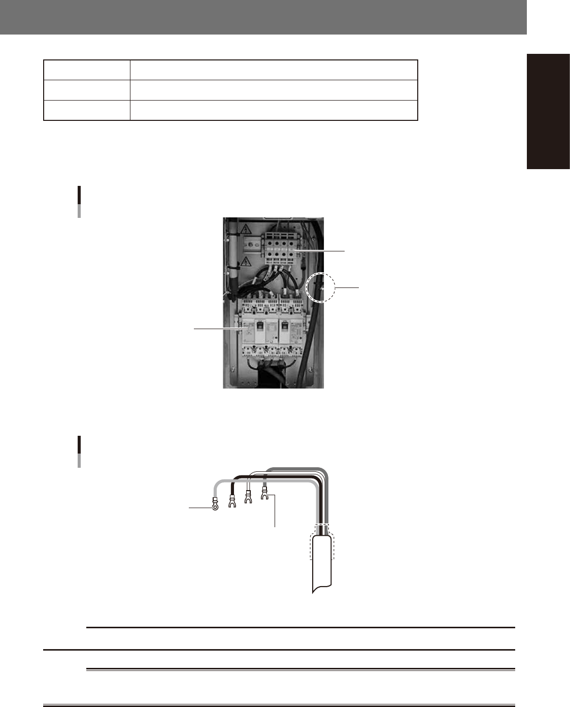
Power input terminal
The power connection terminals are located behind the lower right panel on the front of the machine. Connect the power
cable leads as shown below to the L1, L2, L3, and earth (PE) on the power terminal block.
Power input terminal (L1, L2, L3),
protective earth
Cable is clamped.
Main breaker
Power input terminal
23A01-M6-00
n
Power cable example
Ring tongue terminal
Fork tongue terminal
Power cable termination
L1
L2
L3
PE
L=350mm
23A02-M6-00
c
CAUTION
Use a power cable whose conductor cross-section area is greater than 5.5mm
2
(AWG12).
w
WARNING
TO AVOID THE RISK OF ELECTRICAL SHOCK, MAKE SURE THAT THE POWER SOURCE IS OFF BEFORE CONNECTING THE
POWER CABLE. ALSO MAKE SURE THAT THE GROUND CABLE IS SECURELY CONNECTED TO THE MACHINE.