YSi-X_Ope_E.pdf - 第72页
4-11 4 Maintenance 6 Remo ve the diffuser plate. Using the Phillips screwdriver , remove the four screws holding the diffuser plate and remove the diffuser plate. 53406-M6-00 7 Clean the diffuser plate. Remove dirt and d…
4-10
4
Maintenance
4. Weekly inspection
n
NOTE
Before beginning work, remove the rear center panel by referring to section 3.4 “Removing the rear center panel” in
this chapter so that you can open and close the rear safety door. After finishing the work, reattach the rear center
panel.
4.1 Cleaning the camera lighting unit
Dirt or dust particles sticking to the lighting unit of the optical camera can cause recognition errors during
inspection. Weekly inspection and cleaning are recommended to prevent this problem.
c
CAUTION
Do not apply strong force or shock to the camera unit and lighting unit during cleaning. Optical axis adjustment might
become unreliable.
n
Required tools
• Phillips screwdriver
• Lent-free cleaning wipe
• Optical lens brush
c
CAUTION
The inner side of the camera cover uses lead to shield X-rays. Wear gloves for protection from lead when handling the
camera cover.
e
1
Press the emergency stop button.
The machine must be in emergency stop to
ensure safety during work.
c
CAUTION
To ensure safety, make sure that the machine power
switch is off or the emergency stop button is pressed
before starting work.
2
Open the safety door on the rear of
the machine.
3
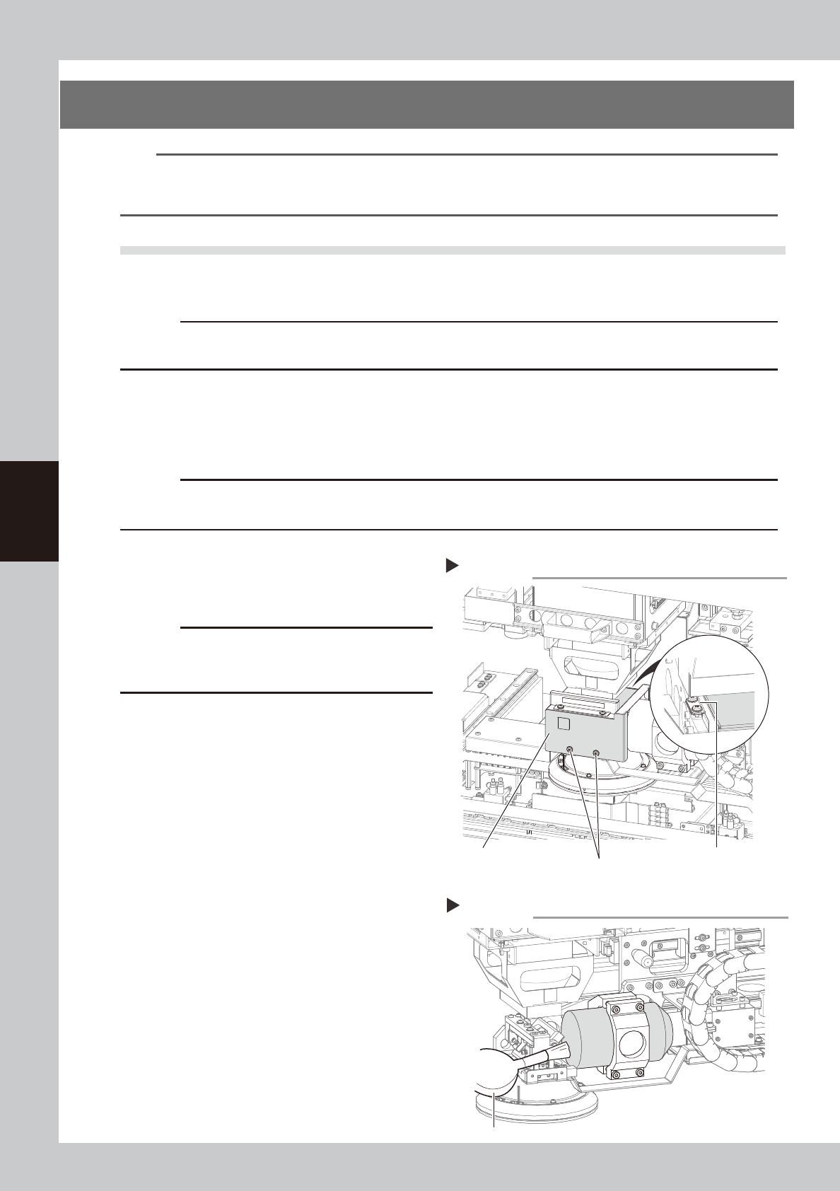
Remove the optical camera cover.
1. Wear gloves for protection from lead and
then use the Phillips screwdriver to
remove the screws securing the camera
cover.
2. Remove the camera cover while being
careful not to drop it and place it on a
flat surface
53404-M6-00
4
Clean the lens surface and mirror
surface.
Use the lens brush to clean dust off the lens
and mirror.
If dust still persists, use lens cleaner to clean
the lens and mirror.
53405-M6-00
5
Reattach the optical camera cover.
To reattach the cover to the optical camera,
reverse the procedure used to remove the
cover.
Removing the optical camera cover
Step 3
Screws securing the cover
(2 screws on outer side)
Screws securing the cover
(2 screws on inner side)
Optical camera cover
Cleaning the lens
Step 4
Optical lens brush
4-11
4
Maintenance
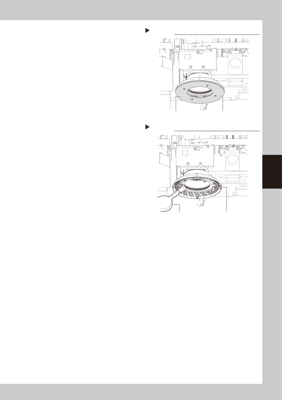
6
Remove the diffuser plate.
Using the Phillips screwdriver, remove the
four screws holding the diffuser plate and
remove the diffuser plate.
53406-M6-00
7
Clean the diffuser plate.
Remove dirt and dust on the entire diffuser
plate with a paper wipe.
8
Remove dust on the lighting unit of
the inspection camera, using a lens
blower brush.
53407-M6-00
9
Reattach the diffuser plate.
Reattach the diffuser plate in the reverse
order of the removal procedure.
Removing the diffuser plate
Step 6
Diffuser plate mounting screw (four screws)
Diffuser plate
Cleaning the lighting for optical camera
Step 8
Optical lens brush
Camera lighting
4-12
4
Maintenance
4.2 Checking the board sensor condition
This equipment uses transmission type fiber sensors as the board sensors. Periodically check that these sensors
correctly operate even when the conveyor rail width is changed.
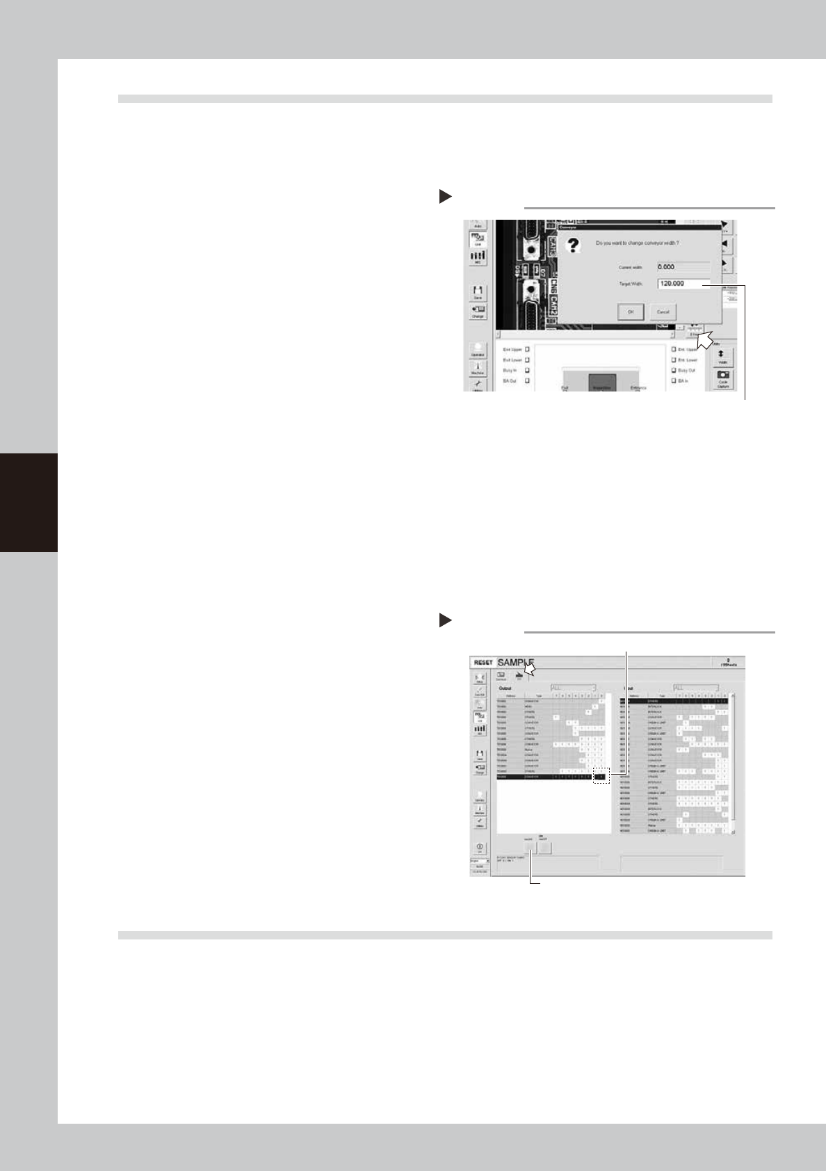
1
Open the [Unit] – [Conveyor] tab.
2
Press the [Width] button to change
the conveyor width.
1. When the “Conveyor” dialog box
appears, enter the maximum conveyor
width (460mm) in the "Target Width" box
and press the [OK] button. The conveyor
width will automatically change to the
specified size.
2. Then, enter the minimum conveyor width
(50mm) in the “Target Width” box and
press the [OK] button. The conveyor
width will automatically change to the
specified size.
54401-M6-00
3
Check whether an error has
occurred.
The conveyor sensor is operating properly
unless an error message appears when the
conveyor width is changed. No further
check is necessary.
n
If an error message appears, then adjust the sensor with the procedure below.
• Adjusting the conveyor sensor
If an error occurred when the conveyor width was
changed, check
to perform auto-tuning
of the
conveyor sensor.
1. Open the [Unit] – [I/O] tab.
2. In the Output list, select “CONVEYOR”
(T01000E0).
3. Press the [ON/OFF] to switch to 0 (OFF)
→
1 (ON)
→
0 (OFF) to perform auto-tuning.
4. Press the [Conveyor] button again to
change the conveyor width as in step 2.
If no error message appears, the sensors
are correctly working.
54402-M6-00
4.3 Checking the board clamp condition
Check the following points when a board is clamped on the conveyor.
1. Check that the board is securely clamped and there is no play.
2. Check that there is no clearance between the board hold plate and the board.
3. Check that the board surface is flush with the conveyor rail upper surface.
4. Check that the board clamp unit moves smoothly.
5. Check that the board is securely clamped by the side clamp and there is no play in the lateral direction.
6. Check that the side clamp moves smoothly.
Changing the conveyor width
Enter the conveyor width here.
Step 2
Changing the conveyor width
3
2