YSi-X_Ope_E.pdf - 第82页
4-21 4 Maintenance 5.2.8 Cleaning and greasing the L Y -axis guides n Required tools • Lent-free cleaning wipe • Grease gun • Specified grease (NSL) c CAUTION W ear protective glasses and gloves when handling grease. e 1…
4-20
4
Maintenance
5.2.7 Cleaning and greasing the LY-axis ball screws
n
Required tools
• Phillips screwdriver
• Lent-free cleaning wipe
• Grease gun
• Specified grease (NSL)
c
CAUTION
Wear protective glasses and gloves when handling grease.
e
1
Make the preparations for the
cleaning and greasing work.
1. Press the emergency stop button to put
the machine into emergency stop.
2. Open the [Unit]-[Conveyor] tab and
press the [Stopper] button to raise the
board stopper.
2
Open the front and rear safety
doors of the machine.
3
Remove the grease spattering
prevention cover.
1. Move the conveyor table and X-ray
camera table to the rear side, and use
the Phillips screwdriver to remove the
screws (two each on the front and rear
sides) securing the grease spattering
prevention cover.
2. Move the X-ray camera table to the front
side and remove the grease spattering
prevention cover by pulling it out from
the rear side
.
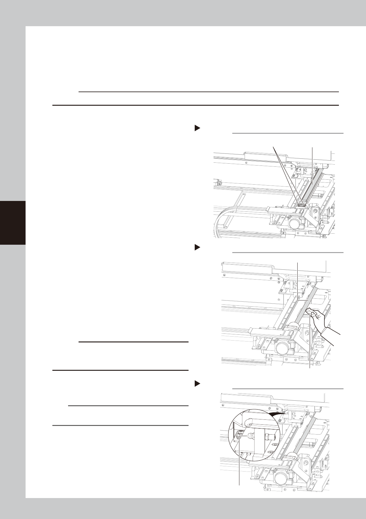
53423-M6-10
4
Clean the ball screws.
1. Facing the rear of the machine, wipe
away the old grease and dirt from the
entire ball screw with a paper wipe.
2.
Move the conveyor table and X-ray camera
table to the rear side, and then wipe the
ball screw from the front side as well.
53424-M6-10
c
CAUTION
Wipe away the old grease and dirt in the lead groove
of the ball screw.
Also check that no debris or residue
remains in the lead groove.
5
Inject new grease.
Use the grease gun to inject the specified
grease (NSL) into the grease nipple (1 place).
53425-M6-10
n
NOTE
See Chapter 5, “Lubrication points”, for details on the
lubrication points and grease gun nozzles.
6
Wipe away excess grease
.
Move the X-ray camera table by hand to the
front and rear several times and then wipe
away excess grease with a paper wipe.
7
Reattach the grease spattering
prevention cover.
Reattach the cover using the reverse of the
removal procedure.
Cleaning the LY-axis ball screw (rear side)
LY-axis ball screw
Step 4
Paper wipe
Removing grease spattering prevention cover (rear side)
Grease spattering
prevention cover
Mounting screw
(two each on front and rear sides)
Step 3
Lubricating the LY-axis ball screw (rear side)
Step 5
Grease nipple
4-21
4
Maintenance
5.2.8 Cleaning and greasing the LY-axis guides
n
Required tools
• Lent-free cleaning wipe
• Grease gun
• Specified grease (NSL)
c
CAUTION
Wear protective glasses and gloves when handling grease.
e
1
Make the preparations for the
cleaning and greasing work.
1. Press the emergency stop button to put
the machine into emergency stop.
2. Open the [Unit]-[Conveyor] tab and
press the [Stopper] button to raise the
board stopper.
2
Open the front and rear safety
doors of the machine.
3
Clean the guides.
1. Move the conveyor table to the front
side and the X-ray camera table to the
rear side.
2. Wipe away the old grease and dirt from
the entire guide with a paper wipe.
3. Move the X-ray camera table to the front
side and wipe the rear guide as well.
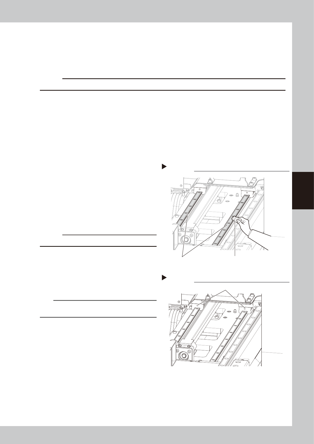
53426-M6-00
c
CAUTION
Also wipe clean the slide groove of each guide.
4
Inject new grease.
Use the grease gun to inject the specified
grease (NSL) into the grease nipple.
There are two grease nipples each for the
left and right guides (total of 4 places).
53427-M6-00
n
NOTE
See Chapter 5, “Lubrication points”, for details on the
lubrication points and grease gun nozzles.
5
Wipe away excess grease
.
Move the X-ray camera table by hand to
the front and rear several times and then
wipe away excess grease with a paper
wipe.
Cleaning the LY-axis guide (front side)
Step 3
LY-axis guide Paper wipe
Lubricating the LY-axis guide (front side)
Step 4
LY-axis grease nipple (two each for front and rear)
4-22
4
Maintenance
5.3 Inspecting and cleaning the conveyor belt
Inspect the conveyor belt for wear. As the belt wears away, slippages may occur that prevent securely
conveying the boards. It is therefore necessary to make periodic checks for wear of the conveyor belt.
Belt wear may also cause trouble such as erroneous detection of the board sensor due to dust from belt wear
accumulating on the sensor surface, or dust from belt wear accumulating in the belt guide grooves may cause
the belt to stick, etc.
n
Required tools
• Hex wrenches 4mm, 5mm
• Vacuum ASSY (option)
1
Change the conveyor width to a
convenient width for maintenance
work.
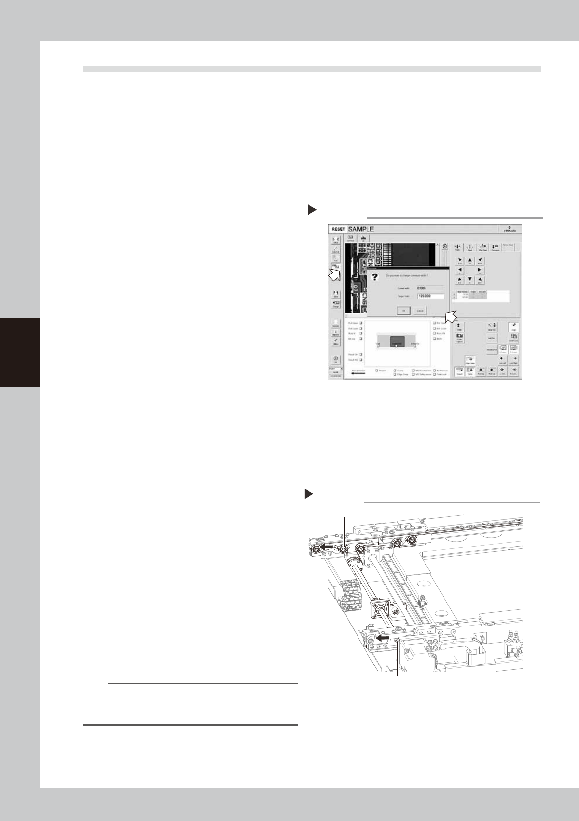
1. Open the [Unit]-[Conveyor] tab and
press the [Width] button to display the
"Conveyor" dialog box.
2. In the "Target Width" box, enter a width
large enough for maintenance work
(about 200mm) and press [OK].
The conveyor is changed to the width
that was just entered.
54403-M6-00
e
2
Make the preparations for the
inspecting and cleaning work.
1. Press the emergency stop button to put
the m machine into emergency stop.
2. Open the [Unit]-[Conveyor] tab and
press the [Stopper] button to raise the
board stopper.
3
Open the front safety door of the
machine.
4
Loosen the tension on the conveyor
belt.
1. Place a square piece of cloth over the
guide and ball screw.
2. Use the hex wrenches (4 mm and 5mm)
to loosen the belt tension (tension pulley)
of the conveyor.
53428-M6-00
5
Remove the conveyor belt.
1. Use the hex wrenches (4 mm and 5mm)
to loosen the pulleys at both ends.
2. Remove the conveyor belt from the
pulley and the belt groove of the board
guide.
TIP
The belt can be removed when the pulleys at both
ends are loosened, so you do not have to loosen the
other pulleys.
6
Check for wear on the board
conveying side of the belt.
After removing the belt, check for wear on
the board conveying side of the belt.
Changing the conveyor width
Step 1
Loosen the tension on the conveyor belt
Step 4
Tension bolt
Tension pulley