YSi-X_Ope_E.pdf - 第88页
4-27 4 Maintenance 3 Check the self-test results. When self-test is complete, the message “X-RA Y READY” reappears at the right end of th e status area. Check the “Max uA” level shown on the “X-ray Information” screen. I…
4-26
4
Maintenance
5.5 X-ray generator
5.5.1 Inspecting the X-ray generator
The YSi-X uses an X-ray generator which has a limited service life. Use the self-test function to make periodic
checks for the service life.
1
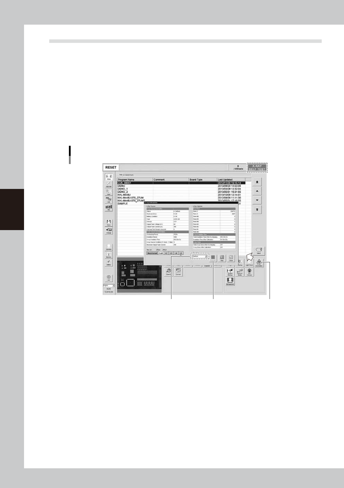
On the Unit screen, press the [X-ray Information] button in the “Utility” group box.
The “X-ray Information” screen appears.
2
Perform self-test.
From the drop-down list in the “Operation" group box, select “Self-test” and press the [Execute] button.
The service life level will be calculated based on the total power-on time and irradiation time. Wait for a
while (about 90 seconds) until the calculation is complete.
During self-test, the message “X-RAY SELF TEST” appears at the right end of the status area.
”X-ray Information” screen
[X-ray Information] button
[Execute] buttonSelect “Self-test”
54404-M6-10
4-27
4
Maintenance
3
Check the self-test results.
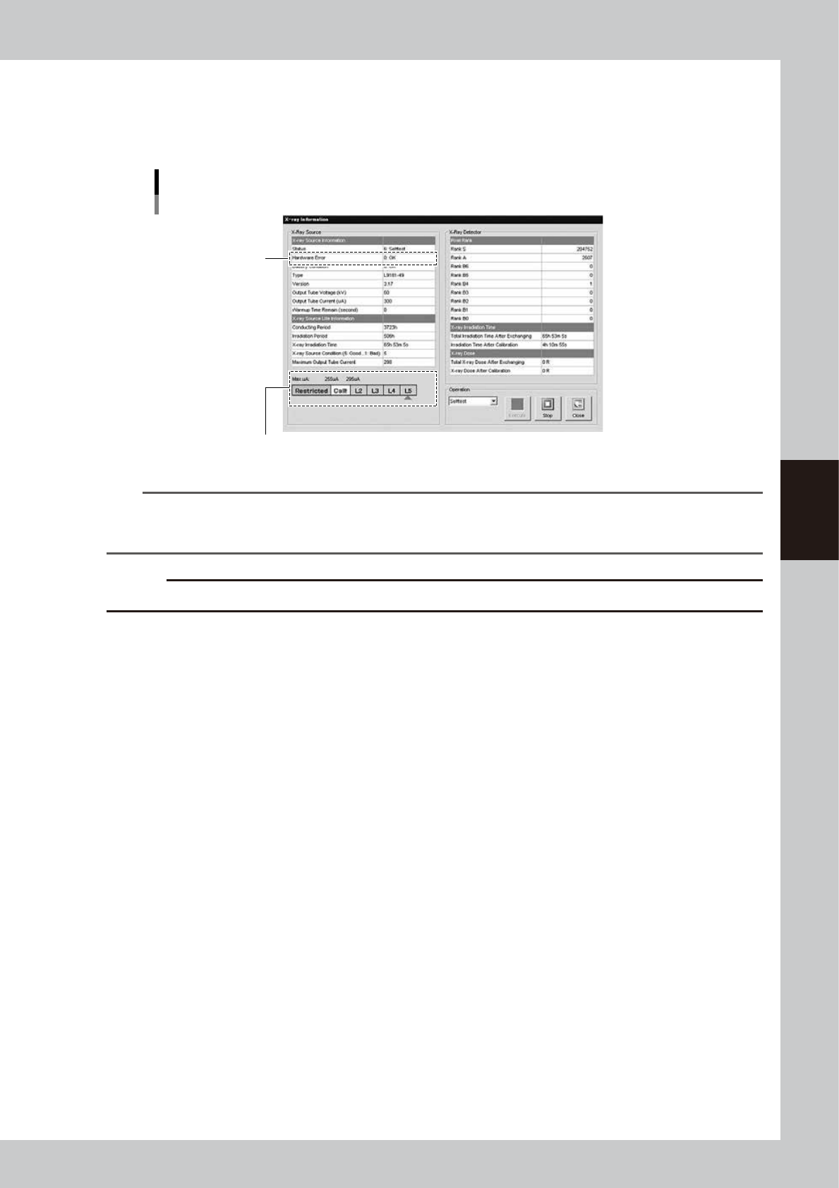
When self-test is complete, the message “X-RAY READY” reappears at the right end of the status area.
Check the “Max uA” level shown on the “X-ray Information” screen. If the level is “L3” or higher, there is
no problem with the X-ray generator.
Self-test results
Check the “Max uA” level
Hardware error
54405-M6-00
n
NOTE
If the “Max uA” level indicates “L2”, a message appears stating that the X-ray source is approaching the replacement
level and asking you to contact the manufacturer. In this case, contact us. We will replace the X-ray source and also
the X-ray detector. If the “Max uA” level indicates “Call!”, this may adversely affect the inspection results.
c
CAUTION
If an error number is displayed in the “Hardware Error” field, please contact us with the error number.
4
Press the [Close] button to finish the measurement.
The “X-ray Information” screen closes and returns to the Setup screen.
4-28
4
Maintenance
6. Three-month inspection
n
NOTE
Before beginning work, remove the rear center panel by referring to section 3.4 “Removing the rear center panel” in
this chapter so that you can open and close the rear safety door. After finishing the work, reattach the rear center
panel.
c
CAUTION
• When handling grease or lubricant, read and follow the precautions listed in section 3.2.2, "Lubricating tools and
grease", in this chapter.
• If abnormal noise is emitted from the ball screw or guide of each axis, then contact our sales representative for
assistance. Disassembly and cleaning of the ball screw or guide by the user will void the warranty.
6.1 Cleaning and greasing the ball screws and guides
6.1.1 Cleaning and greasing the W-axis ball screws
n
Required tools
• Lent-free cleaning wipe
• Specified grease (NSL)
c
CAUTION
Wear protective glasses and gloves when handling grease.
1
Widen the conveyor width to the
maximum.
Perform return-to-origin to widen the
conveyor width to the maximum.
e
2
Press the emergency stop button.
The machine must be in emergency stop to
ensure safety during work.
3
Open the rear safety door of the
machine.
Then move the conveyor table to the rear
side.
4
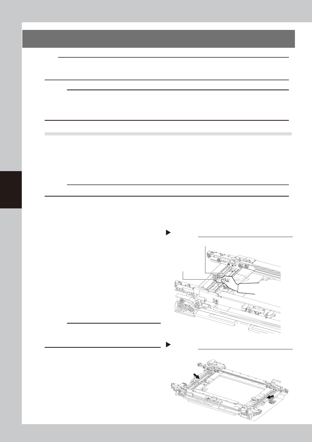
Clean the W-axis ball screw.
Wipe away the old grease and dirt from the
entire ball screw with a paper wipe.
53430-M6-00
c
CAUTION
Wipe away the old grease and dirt in the lead groove
of the ball screw.
Also check that no debris or residue
remains in the lead groove.
5
Apply grease to the ball screw.
Apply the specified grease (NSL) by hand
uniformly over the entire ball screw.
53431-M6-10
6
Wipe away excess grease
.
Wipe away excess grease with a paper
wipe.
Cleaning theW-axis ball screw
Step 4
W-axis ball screw
Paper wipe
Lubricating the W-axis ball screw
Step 5