YSi-X_Ope_E.pdf - 第94页
4-33 4 Maintenance 7. Six-month inspection n NOTE Before beginning work, remove the rear center panel by referring to section 3.4 “Removing the rear center panel” in this chapter so that you can open and close the rear s…
4-32
4
Maintenance
5
Reconnect the air hose to the air
coupler.
After connecting the air hose, check that no
air is leaking.
n
NOTE
When cleaning the filter after cleaning the filter cup,
leave the filter cup removed and advance to the next
section “Cleaning the filter”.
n
Cleaning the air filter and mist filter
1
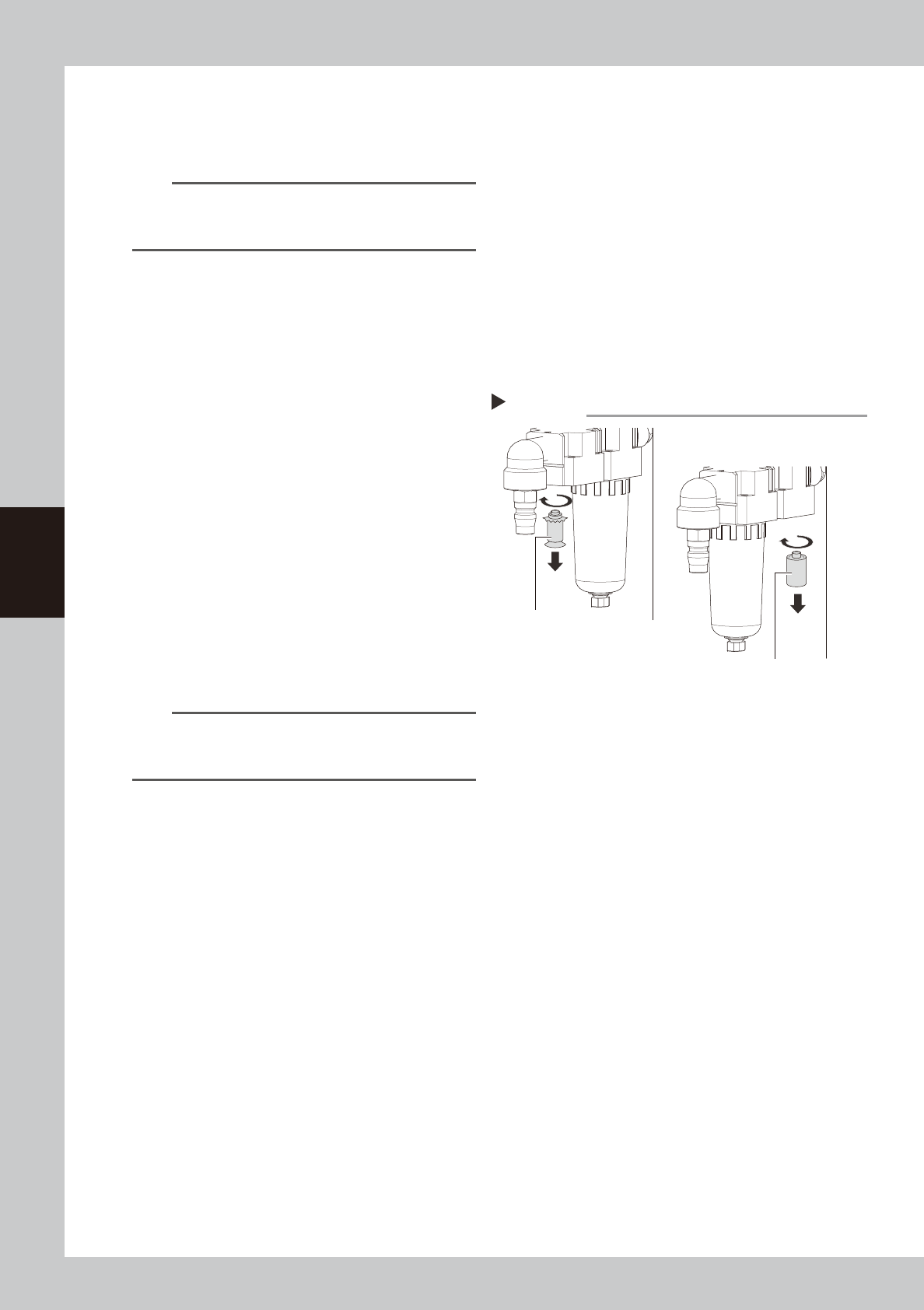
Remove the filter cup.
See the previous procedure in "Cleaning the
filter cup".
2
Remove the filter.
Use the Phillips screwdriver to remove the
mounting screw (by turning it clockwise as
viewed from above) and remove the filter.
53437-M6-00
3
Clean the filter element.
Use the air blow tool to blow away dust and
impurities trapped in the filter element. If the
filter is excessively dirty and cannot be
cleaned, replace it with a new filter.
4
Reattach the filter.
Screw the white disk back in to attach the
air filter to the original position.
5
Reattach the filter cup.
n
NOTE
When cleaning the mist filter, use the same procedure.
To remove the mist filter, unscrew the white portion by
hand (by turning it clockwise as viewed from above).
6
Connect the air coupler.
Connect the air coupler and make sure that
no air leaks.
Removing the filter
Step 2
Mist filter
( MIST FILTER ELEMENT)
Filter
( FILTER ELEMENT)
4-33
4
Maintenance
7. Six-month inspection
n
NOTE
Before beginning work, remove the rear center panel by referring to section 3.4 “Removing the rear center panel” in
this chapter so that you can open and close the rear safety door. After finishing the work, reattach the rear center
panel.
c
CAUTION
• When handling grease or lubricant, read and follow the precautions listed in section 3.2.2, "Lubricating tools and
grease", in this chapter.
• If abnormal noise is emitted from the ball screw or guide of each axis, then contact our sales representative for
assistance. Disassembly and cleaning of the ball screw or guide by the user will void the warranty.
7.1 Cleaning and greasing the ball screws and guides
7.1.1 Cleaning and greasing the HZ-axis ball screws
n
Required tools
• Phillips screwdriver
• Lent-free cleaning wipe
• Grease gun
• Specified grease (NSL)
c
CAUTION
Wear protective glasses and gloves when handling grease.
e
1
Press the emergency stop button.
The machine must be in emergency stop to
ensure safety during work.
2
Open the safety door on the rear of
the machine.
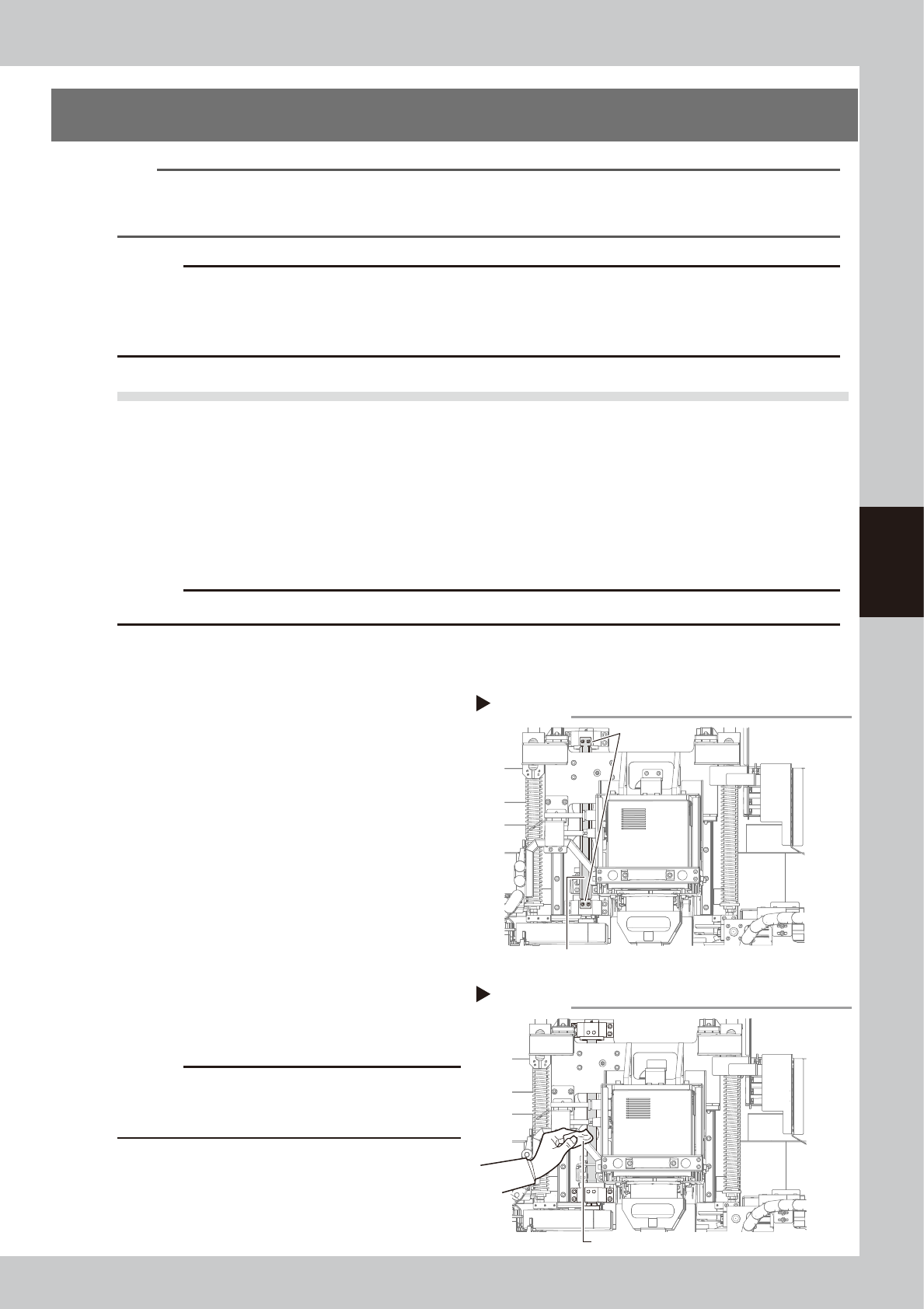
3
Remove the grease spattering
prevention cover.
1. Use the Phillips screwdriver to remove the
bolts (two each on top and bottom)
securing the grease spattering
prevention cover.
2. Remove the grease spattering prevention
cover by pulling it down.
53441-M6-00
4
Clean the ball screws.
Wipe away the old grease and dirt from the
entire ball screw with a paper wipe.
53442-M6-00
c
CAUTION
Wipe away the old grease and dirt in the lead groove
of the ball screw.
Also check that no debris or residue
remains in the lead groove.
Removing grease spattering prevention cover
Step 3
Grease spattering prevention cover
Mounting bolt
Cleaning the HZ-axis ball screw
Step 4
Paper wipe
4-34
4
Maintenance
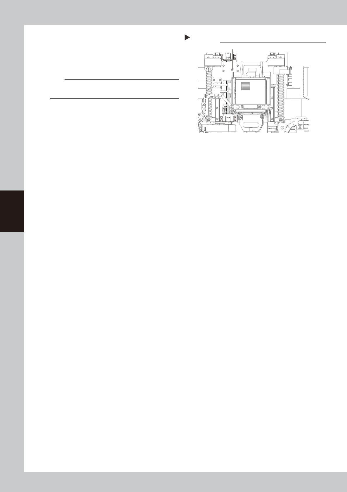
5
Inject new grease.
Use the grease gun to inject the specified
grease (NSL) into the grease nipple (1
place).
53443-M6-00
n
NOTE
See Chapter 5, “Lubrication points”, for details on the
lubrication points and grease gun nozzles.
6
Wipe away excess grease
.
Move the X-ray source up and down and
then wipe away excess grease with a paper
wipe.
7
Reattach the grease spattering
prevention cover.
Reattach the cover using the reverse of the
removal procedure.
Lubricating the LY-axis ball screw
Step 5
Grease nipple