00198442-01_UM_TX-V2_EN.pdf - 第101页
User manual SIPLACE TX V2 3 Technical data and assemblies From software version 711.1 04/2018 3.3 Dimensions and weight 101 3.3 Dimensions and weight 3.3.1 T echnical data - dimensions and weight 3 Length *a Without conv…
3 Technical data and assemblies User manual SIPLACE TX V2
3.2 Ambient conditions and connection values From software version 711.1 04/2018
100
3.2.4 Electrical ratings and energy consumption
3
PLEASE NOTE
Use of a residual current protection device
The low ground leakage current of the system makes it possible to use an upstream re-
sidual current protection device at the customer end. This must be all-current sensitive
(RCD type B).
Electrical ratings
Supply voltage Fuse
Main power supply 3 x 360 V~ to 3 x 415 V~ ± 10 %; 50/60 Hz
3 x 200 V~ to 3 x 220 V~ ± 10 %; 50/60 Hz
*a
3 x 16A characteristic C
3 x 15A characteristic C
*b
Mains power con-
nection
Cable 5 x 2.5 mm² with CEKON connector (3 x 360 V~ to 3 x 415 V~)
Cable 5 x 2.5 mm² without CEKON connector (3 x 200 V~ to 3 x 220 V)
Short circuit rating of
placement machine (SCCR)
*c
10 kA
Energy consumption
With a vacuum pump
*d
Without vacuum pump
*e
Nominal apparent
power
2.6 kVA 2.3 kVA
Nominal active
power
2.00 kW 1.2 kW
*)a With options package
*)b e.g. Siemens circuit breakers in accordance with IEC and UL 489 (order no.: 5SJ4 316-7HG42)
or
EATON Industries circuit breaker FAZ-C16/3-NA 16A 3p (UL 489, CSA C22.2 no. 5, IEC 60947-2)
*)c With the original mains connection cable. The marked short circuit rating (SCCR) relates to the beginning of the original mains
cable. In the case of customer modifications, the factory-set length of the mains cable to the placement machine may not be
shortened nor the factory-set conductor cross-section increased, as this would have a negative impact on the short circuit rating
(SCCR).
*)d Vacuum pump for C&P20 P2 head only.
*)e Optional

User manual SIPLACE TX V2 3 Technical data and assemblies
From software version 711.1 04/2018 3.3 Dimensions and weight
101
3.3 Dimensions and weight
3.3.1 Technical data - dimensions and weight
3
Length
*a
Without conveyor extension and with hand guard
With input conveyor extension
*b
With output conveyor extension
With input and output conveyor extension)
1000 mm
1260 mm
1604 mm
1864 mm
Width
Outer contour of placement machine protection (both tables "inner")
With monitor
Outer contour of placement machine protection (table location 1 "outer")
With monitor
2232 mm
2420 mm
2347 mm
2441mm
Height of placement machine (for PCB conveyor height 950 mm)
Placement machine protection closed
With 2-color indicator lamp
With 3-color indicator lamp
Without indicator lamp (height of packaging)
With folded-up short protective cover 45 degrees position
With folded-up short protective cover 60 degrees position
With folded-up short protective cover 45 degrees position
With folded-up short protective cover 60 degrees position
1500 mm
1690 mm
1735 mm
1500 mm
1960 mm
2070 mm
2050 mm
2175 mm
Floor clearance of placement machine TX1/TX2
(for PCB conveyor height 900 mm)
(for PCB conveyor height 930 mm)
(for PCB conveyor height 950 mm)
120 mm ± 15 mm
150 mm ± 15 mm
170 mm ± 15 mm
Floor clearance of placement machine TX2i
(for PCB conveyor height 900 mm)
(for PCB conveyor height 930 mm)
(for PCB conveyor height 950 mm)
120 mm ± 13 mm
150 mm ± 13 mm
170 mm ± 13 mm
Weight
SIPLACE TX (without feeder modules)
SIPLACE TX (fully equipped with feeder modules)
2036 kg
2150 kg
Location
*c
With table on outside
2.23 m²
2.33 m²
Even floor surface load (without feeder module)
Even floor surface load(with feeder module)
Characteristic floor surface load
6.46 kN/m²
6.79 kN/m²
7.70 kN/m²
Number of placement machine feet 4
Max. noise emissions 75 dB (A)
*)a Measured at the outer contour of the placement machine protection.
*)b Only in the first placement machine of the line.
*)c Measured at the outer contour of the placement machine protection and without conveyor extension.
Important notes
When setting up a placement machine (TX, SX or X-Series S) next to a SIPLACE TX, observe the correct spacing between them. In these
cases, use a suitable conveyor extension to create room of 0.5 m for the operator between the two placement machines.
To achieve top placement performance, fit the first machine in a SIPLACE TX line with an input conveyor extension and the last placement
machine in the line with an output conveyor extension.
3 Technical data and assemblies User manual SIPLACE TX V2
3.3 Dimensions and weight From software version 711.1 04/2018
102
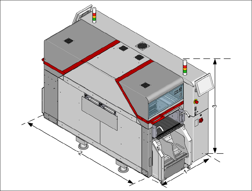
3.3.1.1 Overview of dimensions
3
Fig. 3.3 - 1 Overview of dimensions - example SIPLACE TX2
Example:
(1) Length = 1000 mm
(2) Width = 2232 mm
(3) Height =
1735 mm