00198442-01_UM_TX-V2_EN.pdf - 第104页
3 Technical data and assemblies User manual SIPLACE TX V2 3.3 Dimensions and weight From software version 711.1 04/2018 104 3.3.2 Maneuvering dist ances for component trolleys 3 Fig. 3.3 - 3 Maneuvering distances of comp…
User manual SIPLACE TX V2 3 Technical data and assemblies
From software version 711.1 04/2018 3.3 Dimensions and weight
103
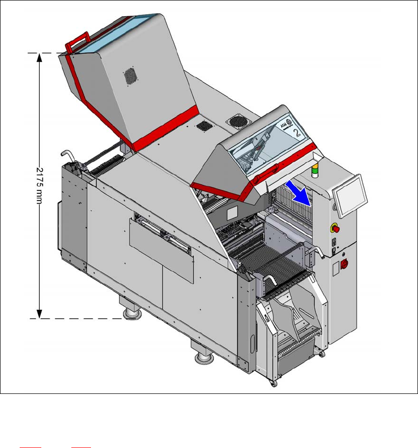
3.3.1.2 Height of the folded up protective cover
3
Fig. 3.3 - 2 Height of the folded-up protective cover - dimensions in millimeters (example of SIPLACE TX2 shown)
– With folded-up long protective cover in 60 degrees position (for more values see section
3.3.1
, page 101).
The specified dimensions refer to the max. PCB conveyor height of 950 mm.
3 Technical data and assemblies User manual SIPLACE TX V2
3.3 Dimensions and weight From software version 711.1 04/2018
104
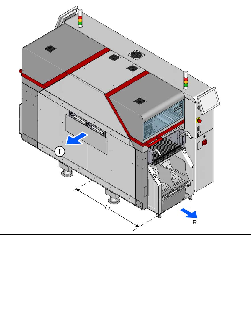
3.3.2 Maneuvering distances for component trolleys
3
Fig. 3.3 - 3 Maneuvering distances of component trolleys in SIPLACE TX placement machines
The maneuvering distance R of the component trolleys in the SIPLACE TX placement machines
is as follows:
3
Location (outside) Location (inside)
R Maneuvering distance 800 mm 680 mm
L1 Placement machine center to outer edge of
component trolley TX
1222 mm 1102 mm
User manual SIPLACE TX V2 3 Technical data and assemblies
From software version 711.1 04/2018 3.3 Dimensions and weight
105
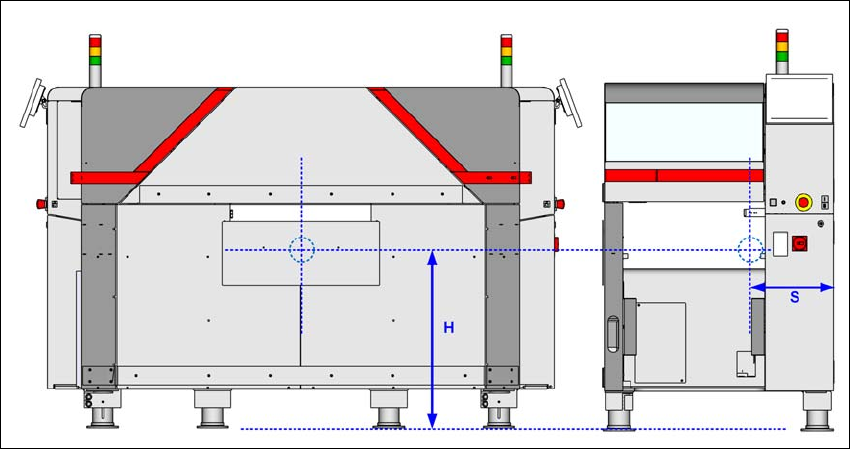
3.3.3 Center of gravity
3
Fig. 3.3 - 4 Center of gravity in millimeters
Center of gravity S = 420 mm / H = 750 mm