00198442-01_UM_TX-V2_EN.pdf - 第110页
3 Technical data and assemblies User manual SIPLACE TX V2 3.5 Placement head From software version 711.1 04/2018 110 3.5.2 Sensor for the component reject bin The sensor for the component reject bin monitor s wh ether th…
User manual SIPLACE TX V2 3 Technical data and assemblies
From software version 711.1 04/2018 3.5 Placement head
109
3.5.1.2 Technical data for SIPLACE SpeedStar (C&P20 P2)
3
SIPLACE SpeedStar(C&P20 P2)
With component camera type 48
Component range
*a
*)a Please note that the placeable component range is also affected by the pad geometry, the customer-
specific standards, the component packaging tolerances and the component tolerances.
0.12 mm x 0.12 (0201 metric) to 2220, Melf, SOT, SOD, Bare-
Die, Flip-Chip
Component spec.
Max. height
Min. lead pitch
Min. lead width
Min. ball pitch
Min. ball diameter
Min. dimensions
Max. dimensions
Max. weight
2 mm
*b
/ 4 mm
70 µm
30 µm
100 µm
50 µm
0.12 mm x 0.12 mm
8.2 mm x 8.2 mm
1 g
*)b Only 2 mm possible for SIPLACE TX2i.
Programmable set-down
force
Touchless Placement, 1.3 N ± 0.5 N (standard)
0.5 N - 4.5 N
Nozzle types 60xx
X/Y accuracy
*c
*)c The accuracy values fulfill the conditions in the SIPLACE scope of supply and services.
± 25 µm/3σ
Angular accuracy ± 0.5° / 3σ
Illumination level 5
3 Technical data and assemblies User manual SIPLACE TX V2
3.5 Placement head From software version 711.1 04/2018
110
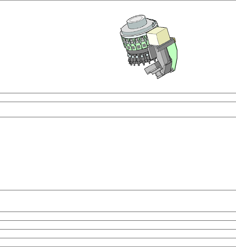
3.5.2 Sensor for the component reject bin
The sensor for the component reject bin monitors whether the reject bin is seated correctly in its
mount.
– If the reject bin was not inserted correctly, the machine cannot be started.
– If the reject bin jumps out of its mount during the placement process, the machine is stopped
immediately to avoid a head crash.
3.5.3 Vacuum pump
Item no. 03157734-xx vacuum pump
Item no. 03165711-xx frequency converter (optional)
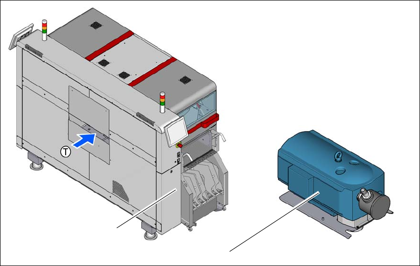
3.5.3.1 Overview
The vacuum pump is a standard for the SIPLACE SpeedStar and is fitted behind the cover at lo-
cation 1, in the placement machine frame.An optional frequency converter is available
3
Fig. 3.5 - 2 Overview - vacuum pump
(1) Installation location for vacuum pump
(2) Vacuum pump
(T) Direction of PCB transport
(1)
(2)
User manual SIPLACE TX V2 3 Technical data and assemblies
From software version 711.1 04/2018 3.5 Placement head
111
3.5.3.2 Safety instructions for vacuum pumps
3
3.5.3.3 Description
Only the SIPLACE SpeedStar can be operated with the vacuum pump. In the SIPLACE TX V2,
the default configuration is a SIPLACE SpeedStar with vacuum pump.
There are a maximum of two SIPLACE SpeedStar heads and one vacuum pump.
When operated with a vacuum pump, the compressed air consumption for the SIPLACE Speed-
Star is reduced considerably. The running costs will fall according to the energy costs incurred.
The vacuum pump is switched on and off with the main switch of the placement machine.
3
3
3.5.3.4 Maintenance instructions
Observe the additional maintenance instructions for the vacuum pump.
Read the relevant section in the maintenance manual for your placement machine.
WARNING
Please observe the safety instructions in the vacuum pump user manual supplied.
If you use a frequency converter to operate the vacuum pump, you should take a
higher leakage current into account. The operator must observe the installation reg-
ulations which result from this (a second protective (earth) conductor may be re-
quired).
PLEASE NOTE
The vacuum pump is NOT approved for operation in the clean room for ISO class 7.
PLEASE NOTE
The compressed air consumption values can be found in section 3.2.3
, page 99.