00198442-01_UM_TX-V2_EN.pdf - 第135页
User manual SIPLACE TX V2 3 Technical data and assemblies From software version 711.1 04/2018 3.7 PCB conveyor system 135 3.7.5 PCB camera, type 34, digit al 3.7.5.1 Structure 3 Fig. 3.7 - 4 PCB camera, type 34, digital …
3 Technical data and assemblies User manual SIPLACE TX V2
3.7 PCB conveyor system From software version 711.1 04/2018
134
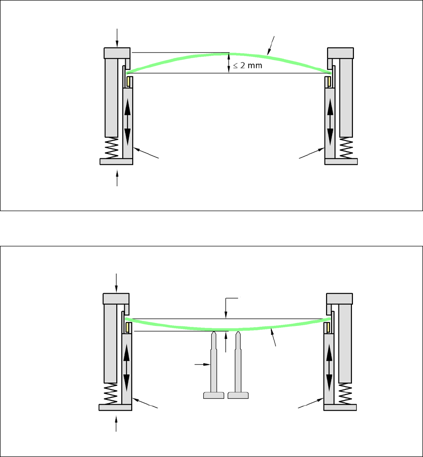
3.7.4.2 PCB warpage during placement
A warpage of 2 mm can lead to problems focussing on local fiducials and ink spots in the middle
of the PCB. The PCB camera's focus is 2 mm. When all the tolerances are taken into account, this
value is reduced to 1.5 mm. Also note that the component height is reduced by the warpage.
3
3
PCB warpage down, max. 0.5 mm
3
Use magnetic pin supports to achieve this value.
Movable clamping device
Fixed clamped edge
Printed circuit board
Conveyor side wall
Printed circuit board
Magnetic pin
support
Movable clamping device
Fixed clamped edge
Conveyor side wall
0.5 mm
User manual SIPLACE TX V2 3 Technical data and assemblies
From software version 711.1 04/2018 3.7 PCB conveyor system
135
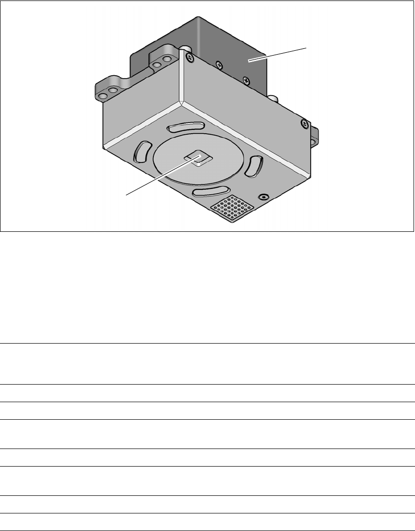
3.7.5 PCB camera, type 34, digital
3.7.5.1 Structure
3
Fig. 3.7 - 4 PCB camera, type 34, digital
(1) PCB camera lens and illumination
(2) Camera amplifier
3.7.5.2 Technical data
3
(1)
(2)
PCB fiducials Up to 3 (subpanels and multiple panels)
Up to 6 for the Long board option (Optional PCB fiducials are
output by the optimization).
Local fiducials Up to 2 per PCB (may be of different type)
Library memory Up to 255 fiducial types per subpanel
Image analysis Edge detection method (Singular feature) based on grayscale
values
Illumination type Front-illumination (3 levels, programmable as required)
Detection time per
fiducial/bad fiducial
20 ms - 200 ms
Field of vision 5.78 mm x 5.78 mm
Distance from the focus plane 28 mm

3 Technical data and assemblies User manual SIPLACE TX V2
3.7 PCB conveyor system From software version 711.1 04/2018
136
3.7.5.3 Fiducial criteria
3
3.7.5.4 Ink spot criteria
3
Locate 2 fiducials
Locate 3 fiducials
X-/Y-position, rotation angle, mean PCB distortion
additional: shearing, distortion separately in X and Y direction
Fiducial shapes Synthetic fiducials: circle, cross, square, rectangle, diamond,
circular, square and rectangular contours, double cross
Pattern: any
Fiducial surface
Copper
Tin
Without oxidation and solder resist
Warp ≤ 1/10 of structure width, both with good contrast to
environment
Dimensions of synthetic fiducials
Min. X/Y size for circle and rectangle:
Min. X/Y size for annulus and rectangle:
Min. X/Y size for cross:
Min. X/Y size for double-cross:
Min. X/Y size for rhombus:
Min. frame width for annulus and rectangle:
Min. bar width / bar distance for cross, double-cross:
Max. X/Y size for all fiducial shapes:
Max. bar width for cross, double-cross:
Min. tolerances, general:
Max. tolerances, general:
0.25 mm
0.3 mm
0.3 mm
0.5 mm
0.35 mm
0.1 mm
0.1 mm
3 mm
1.5 mm
2% of nominal dimension
20% of nominal dimension
Dimensions of patterns
Min. size
Max. size
0.5 mm
3 mm
Fiducial environment Clearance around reference fiducial not necessary if there is no
similar fiducial structure in the search area.
Methods - Synthetic fiducial recognition method
- Mean grayscale value
- Histogram method
- Template matching
Shapes and sizes of fiducials/
structures for
Synthetic fiducials
Other methods
For dimensions of synthetic fiducials, see Section 3.7.5.3
Fidu-
cial criteria, page 136.
Min. 0.3 mm
Max. 5 mm
Masking material Good coverage
Recognition time Depends on the method: 20 ms - 0.2s