00198442-01_UM_TX-V2_EN.pdf - 第136页
3 Technical data and assemblies User manual SIPLACE TX V2 3.7 PCB conveyor system From software version 711.1 04/2018 136 3.7.5.3 Fiducial criteria 3 3.7.5.4 Ink spot criteria 3 Locate 2 fiducials Locate 3 fiducials X-/Y…
User manual SIPLACE TX V2 3 Technical data and assemblies
From software version 711.1 04/2018 3.7 PCB conveyor system
135
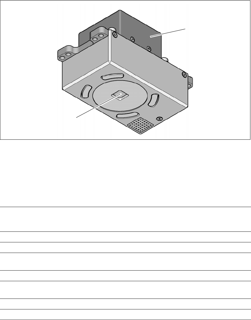
3.7.5 PCB camera, type 34, digital
3.7.5.1 Structure
3
Fig. 3.7 - 4 PCB camera, type 34, digital
(1) PCB camera lens and illumination
(2) Camera amplifier
3.7.5.2 Technical data
3
(1)
(2)
PCB fiducials Up to 3 (subpanels and multiple panels)
Up to 6 for the Long board option (Optional PCB fiducials are
output by the optimization).
Local fiducials Up to 2 per PCB (may be of different type)
Library memory Up to 255 fiducial types per subpanel
Image analysis Edge detection method (Singular feature) based on grayscale
values
Illumination type Front-illumination (3 levels, programmable as required)
Detection time per
fiducial/bad fiducial
20 ms - 200 ms
Field of vision 5.78 mm x 5.78 mm
Distance from the focus plane 28 mm

3 Technical data and assemblies User manual SIPLACE TX V2
3.7 PCB conveyor system From software version 711.1 04/2018
136
3.7.5.3 Fiducial criteria
3
3.7.5.4 Ink spot criteria
3
Locate 2 fiducials
Locate 3 fiducials
X-/Y-position, rotation angle, mean PCB distortion
additional: shearing, distortion separately in X and Y direction
Fiducial shapes Synthetic fiducials: circle, cross, square, rectangle, diamond,
circular, square and rectangular contours, double cross
Pattern: any
Fiducial surface
Copper
Tin
Without oxidation and solder resist
Warp ≤ 1/10 of structure width, both with good contrast to
environment
Dimensions of synthetic fiducials
Min. X/Y size for circle and rectangle:
Min. X/Y size for annulus and rectangle:
Min. X/Y size for cross:
Min. X/Y size for double-cross:
Min. X/Y size for rhombus:
Min. frame width for annulus and rectangle:
Min. bar width / bar distance for cross, double-cross:
Max. X/Y size for all fiducial shapes:
Max. bar width for cross, double-cross:
Min. tolerances, general:
Max. tolerances, general:
0.25 mm
0.3 mm
0.3 mm
0.5 mm
0.35 mm
0.1 mm
0.1 mm
3 mm
1.5 mm
2% of nominal dimension
20% of nominal dimension
Dimensions of patterns
Min. size
Max. size
0.5 mm
3 mm
Fiducial environment Clearance around reference fiducial not necessary if there is no
similar fiducial structure in the search area.
Methods - Synthetic fiducial recognition method
- Mean grayscale value
- Histogram method
- Template matching
Shapes and sizes of fiducials/
structures for
Synthetic fiducials
Other methods
For dimensions of synthetic fiducials, see Section 3.7.5.3
Fidu-
cial criteria, page 136.
Min. 0.3 mm
Max. 5 mm
Masking material Good coverage
Recognition time Depends on the method: 20 ms - 0.2s

User manual SIPLACE TX V2 3 Technical data and assemblies
From software version 711.1 04/2018 3.8 SIPLACE tape feeder modules for SIPLACE TX
137
3.8 SIPLACE tape feeder modules for SIPLACE TX
The SIPLACE TX uses the SIPLACE SmartFeeder X and the SIPLACE SmartFeeder Xi. The
specified SIPLACE tape feeder modules are compatible with the SIPLACE TX changeover tables.
Key features of the SIPLACE tape feeder modules include high pickup position precision, online
programming and simple handling of feeder module changeovers during the placement process.
The power supply to the feeder modules is contactless and uses an inductive interface. Each
feeder module communicates with the feeder module control unit (FCU) via two optoelectronic
channels (optical fiber). The two interfaces form the EDIF assembly (energy and data interface).
3.8.1 SIPLACE tape feeder module
3.8.1.1 Tape material
The tape width spectrum for SIPLACE TX ranges from 4 mm to 56 mm. The tape material is blister
or paper. Component tapes with a permanently adhesive cover foil (PSA foil) can also be pro-
cessed as a default.
The design of the tape feeder modules was based on the following tape standards:
DIN EN 60286-3 (12/1998) / IEC 60286-3 (12/1997)
JIS C 0806-3 (1999)
ANSI/EIA 481-C (10/2003)
IEC 60286-3-2 3
3.8.1.2 Manual removal of tantalum capacitors which were not picked up
To prevent tantalum capacitors which were not picked up from causing the tape material to burn
when it is cut, the user interface has been extended to include the option "Stop immediately on
pickup error". This option must be enabled in SIPLACE Pro. On the placement machine, the com-
ponent that was not picked up is stepped forward again until it is ready for removal from the com-
ponent tape. The track is deactivated and the operator is sent an error message to remind him to
pick up the tantalum component from the tape. If an alternative track is available, the placement
machine continues placing. The operator is able to stop the placement machine, however, and re-
move the tantalum component. If no alternative track is available and it is not possible to continue
placement with other components, the machine will stop. At this point, the operator can again re-
move the tantalum component and acknowledge the error. Once the operator has restarted the
placement machine, placement is continued and components are picked up from the track that is
now enabled once more.
3
PLEASE NOTE
This software function is also a good idea for expensive components.
Please observe the safety instructions for capacitors on metallic powder basis (see section 2.4.3,
page 64
).