00198442-01_UM_TX-V2_EN.pdf - 第150页
3 Technical data and assemblies User manual SIPLACE TX V2 3.9 Component trolley From software ver sion 711.1 04/2018 150 3.9.3 Fiducials on the SIPLAC E TX-Series component trolley 3 Fig. 3.9 - 3 Fiducials on the SIPLACE…
User manual SIPLACE TX V2 3 Technical data and assemblies
From software version 711.1 04/2018 3.9 Component trolley
149
3
3
3
3.9.2 Technical data
3
3
CAUTION
Risk of breaking handles!
Risk of breaking handles when transporting the component trolley.
When transporting the component trolley, do not lift it by its handles.
Only use the handles to push the component trolley.
Use a fork-lift if you want to transport the component trolley or lift it off the pallet.
CAUTION
Risk of component trolley tilting
There is a risk of tilting when moving the component trolley over obstacles and sloping
surfaces.
Do not move the component trolley over obstacles and do not bump it against ob-
jects.
When moving along sloping surfaces, make sure that the component trolley does not
roll away by itself, so that it could tip over.
PLEASE NOTE
All component trolleys must be docked onto the
placement machine in order to operate it.
Fill any free locations with dummy feeder modules as described in
section 2.5.4
, page 82.
Length x width 727 mm x 592 mm
Height of the changeover table 890 mm for 900 mm PCB conveyor height
920 mm for 930 mm PCB conveyor height
940 mm for 950 mm PCB conveyor height
Number of locations 40 (Smart Feeder 8 mm X tape feeder mod-
ule)
Weight
Without feeder modules
With feeder module at all locations
80 kg
140 kg
Tape reel diameter
Tape container
In two rows as an option
to 330.2 mm (13")
to 177.8 mm (7")
3 Technical data and assemblies User manual SIPLACE TX V2
3.9 Component trolley From software version 711.1 04/2018
150
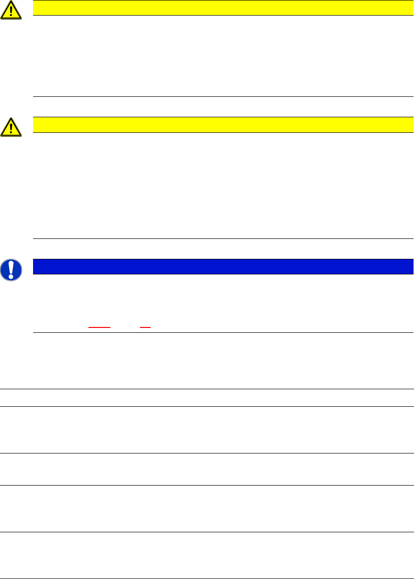
3.9.3 Fiducials on the SIPLACE TX-Series component trolley
3
Fig. 3.9 - 3 Fiducials on the SIPLACE TX-Series component trolley
(1) Fiducials on the component trolley
Once the SIPLACE TX component trolley has been docked in, the placement machine measures
the fiducials on the component trolley.
In the case of components with an edge length less than 0.5 mm, meaning 0402 components and
smaller, the position of the component is determined with the tape pocket, when the setup is spec-
ified or when the start button is pressed after the table or feeder has been removed.
(1)
User manual SIPLACE TX V2 3 Technical data and assemblies
From software version 711.1 04/2018 3.9 Component trolley
151
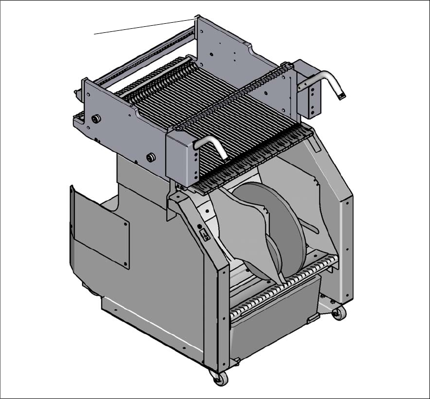
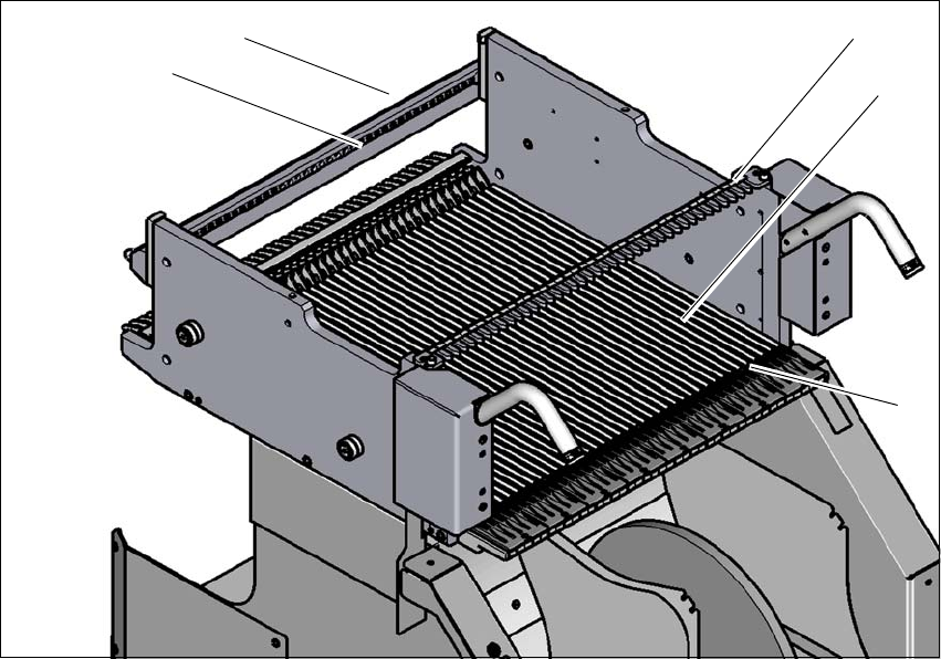
3.9.4 SIPLACE TX-Series changeover table
The front slider guides of the feeder modules are placed on the insertion aid. As it is pushed in,
the guides of the feeder module slide on the guide profile as far as the stop bar. A centering hole
on the stop bar holds the "front" centering pin of the X feeder module. At the same time, the locking
latch of the changeover table latches onto the locking roller of the feeder module. The "back" cen-
tering pin on the top of the feeder module is held by the recess in the centering bar.
3
Fig. 3.9 - 4 Changeover table, SIPLACE TX-Series, rear view
(1) Insertion aid
(2) Guide profile (Ω profile)
(3) Centering bar for holding the "back" centering pin for X feeder modules
(4) Centering holes
(5) Stop bar
(1)
(2)
(3)
(4)
(5)