00198442-01_UM_TX-V2_EN.pdf - 第165页
User manual SIPLACE TX V2 4 Setting up and commissioning From software version 711.1 04/2018 4.4 Infrastructure at the installation location 165 4.4 Infrastructure at the inst allation location 4 4.4.1 Recommendations fo…

4 Setting up and commissioning User manual SIPLACE TX V2
4.3 Transporting the placement machine From software version 711.1 04/2018
164
Transport the placement machine to its target position in your production environment.
Place the placement machine in the line (see section 4.5.5, page 181).
4.2.7 Delivery configuration for placement machine
The machine is configured as follows when delivered:
– The lanes of the dual conveyor are set to a width of 210 mm. This width setting will be import-
ant when fine-tuning the placement machine.
– Both monitors are dismantled.
– Both indicator lamps are dismantled.
– All gantry axes are fixed with shipping braces (see section 4.6
, page 193).
4.3 Transporting the placement machine
The machine may only be lifted and transported with the fork-lift at the output side. The diagram
4.2 - 4
, page 163 shows the fork-lift attachment points on the placement machine for lifting the
placement machine off the pallet or transporting it without the pallet.
4
4.3.1 Safety instructions during placement machine transportation
During transportation, always follow the safety instructions in section 4.1, page 155).
4
PLEASE NOTE
If the machine is at its place of final use and should be integrated into a line, it may also
be lifted to the actual locations with a pallet truck. See also section 4.5.5
, page 181).

User manual SIPLACE TX V2 4 Setting up and commissioning
From software version 711.1 04/2018 4.4 Infrastructure at the installation location
165
4.4 Infrastructure at the installation location
4
4.4.1 Recommendations for foundation quality
The floor on which the placement machine is installed must be firm and level, as dynamic forces
could cause vibrations when the placement machine is operated. The degree of vibration depends
on the construction of the foundation. The following are suitable provided that the floor loading pa-
rameters, etc., are not exceeded:
– Reinforced concrete ceiling constructions, e.g. ceilings in production halls
– Reinforced concrete floor slabs, e.g. concrete floors in production halls without a basement
– Rooms with double floors, provided that a stable foundation is included in the space between
them. The same setup conditions apply to this intermediate foundation, which can be made
from steel girders or concrete.
4
4.4.1.1 Ground levelness
The floor underneath the placement machine may not exceed an incline of 0.63%. This corre-
sponds to an incline of 5 mm over a distance of 800 mm (e.g. the width of a changeover table).
4.4.1.2 Machine weight and floor surface load
The machine weight and floor surface load can be found in section 3.3.1, page 101.
PLEASE NOTE
Also observe the document "Network and compressed air configuration for SMD sys-
tems" (German+English, Item No. 00197548-xx), which is supplied with your SIPLACE
placement machine.
4 Setting up and commissioning User manual SIPLACE TX V2
4.4 Infrastructure at the installation location From software version 711.1 04/2018
166
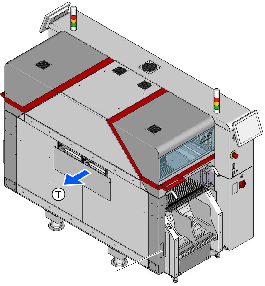
4.4.2 Compressed air supply
Fig. 4.4 - 1 Position of compressed air supply in the placement machine
(1) Installation position of compressed air supply at location 2
(T) Direction of travel
1