00198442-01_UM_TX-V2_EN.pdf - 第171页
User manual SIPLACE TX V2 4 Setting up and commissioning From software version 711.1 04/2018 4.4 Infrastructure at the installation location 171 4.4.3.3 Power supply cable - specification The placement machine is deliver…
4 Setting up and commissioning User manual SIPLACE TX V2
4.4 Infrastructure at the installation location From software version 711.1 04/2018
170
4.4.3.1 Danger notes
4
4
4.4.3.2 Checking the main power supply
Check whether the power supply complies with the prescribed machine specifications (see table
in section 3.2.4
, page 100).
4
DANGER
Dangerous voltage levels!
The machine is supplied with 3 x 360 V~ to 3 x 415 V ± 10 %, 50/60 Hz or optionally with
3 x 200 V~ to 3 x 220 V~ ± 10 %; 50/60 Hz mains voltage. This means that some parts of
the system carry potentially lethal voltages - even when switched off at the main power
switch.
Incorrect handling of this placement machine can therefore result in death or severe injury
or considerable damage to equipment.
Always follow the applicable accident prevention and DIN regulations (particularly EN
60204, part 1 or IEC 60204, part 1) and the applicable regulations in your own coun-
try.
The covers over the power supply unit may ONLY be opened by appropriately quali-
fied and trained personnel.
DANGER
Lethal voltages in the power supply unit!
The power supply unit has components (capacitors) which can still conduct potentially le-
thal voltages for approx. 5 minutes, even when the placement machine is switched off and
the mains plug has been disconnected.
Wait at least 5 minutes before you perform work on the power supply unit.
Test to check that there is no remaining voltage supply. See the procedure described
in the service manual.
Only ASM Assembly Systems GmbH&Co.KG service engineers or the machine
owner's service engineers, who have been trained by ASM, may perform work on the
power supply and the safety cutoff (CBS).
PLEASE NOTE
Load peaks in power supply
For technical reasons, load peaks occur in the power supply.
Please contact your power company to clarify the mains impedance, if necessary.
User manual SIPLACE TX V2 4 Setting up and commissioning
From software version 711.1 04/2018 4.4 Infrastructure at the installation location
171
4.4.3.3 Power supply cable - specification
The placement machine is delivered with a mains power cable with the following specifications:
– 5 x 2.5 mm² for 3 x 200 V~ to 3 x 415 V ± 10 %, 50/60 Hz mains voltage for a cable length of
up to 5 meters to the machine mains power connection.
4
4
4
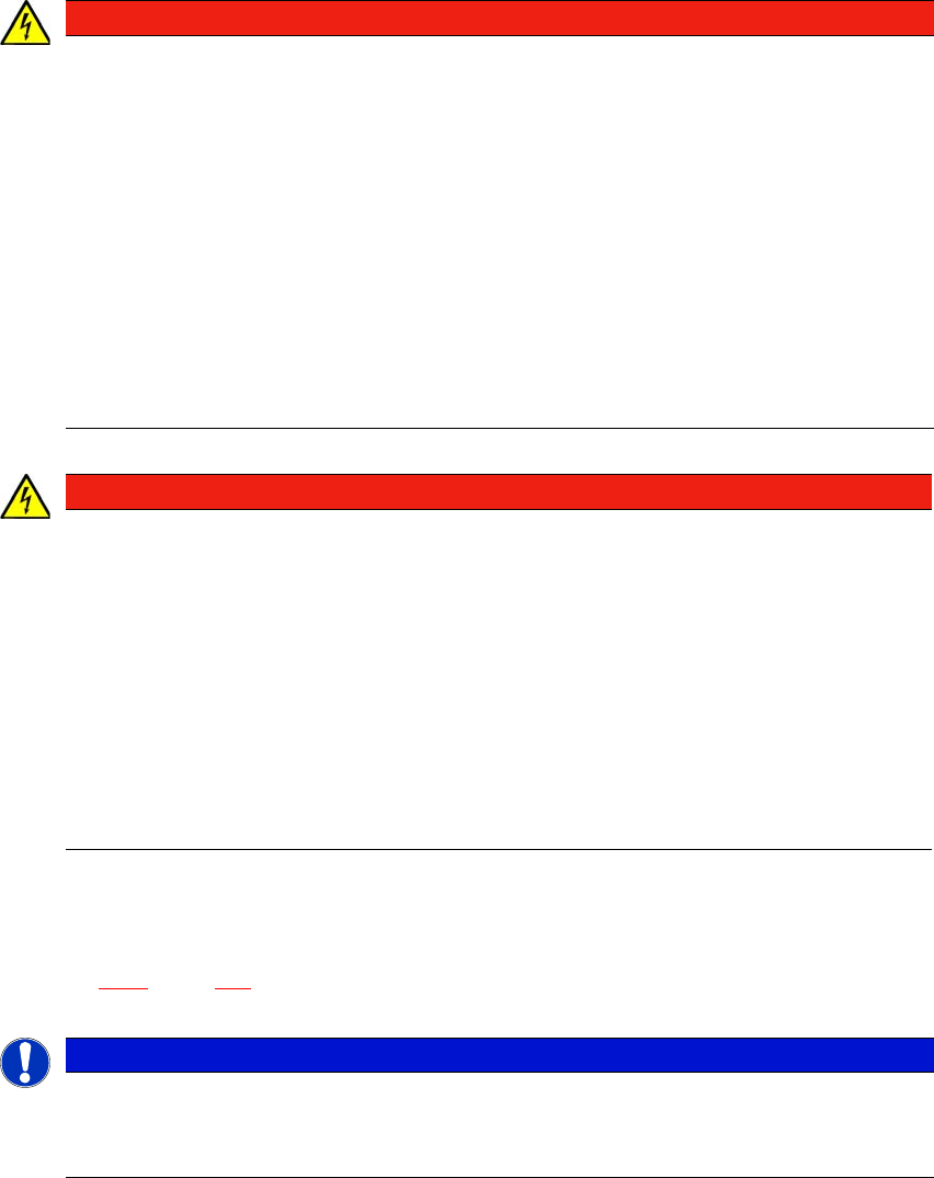
Fig. 4.4 - 4 Terminal panel for connecting the power cable
The mains supply cable is connected to the connection terminals (1) in sector 1 at the output end.
WARNING
Cross-section and length of mains connection cable
The cross-section and length of the mains connection cable influence the Short-Circuit-
Current-Rating (SCCR) of the placement machine.
When replacing the mains connection cable, do not increase the cross-section of the
wires or shorten the length of the cable.
WARNING
Clear marking of electrical leads!
The electrical leads to each individual placement machine and to the options installed
must be clearly labeled and easily assignable.
The regulations of the country in which the machine is operated apply.
(1)
4 Setting up and commissioning User manual SIPLACE TX V2
4.4 Infrastructure at the installation location From software version 711.1 04/2018
172
4.4.3.4 Mains connection - delivery configuration
The mains power connection is configured according to the power supply of the country con-
cerned.
– The placement machine is configured for voltages of 3 x 200 V~ to 3 x 220 V~ ± 10 %; 50/60
Hz.
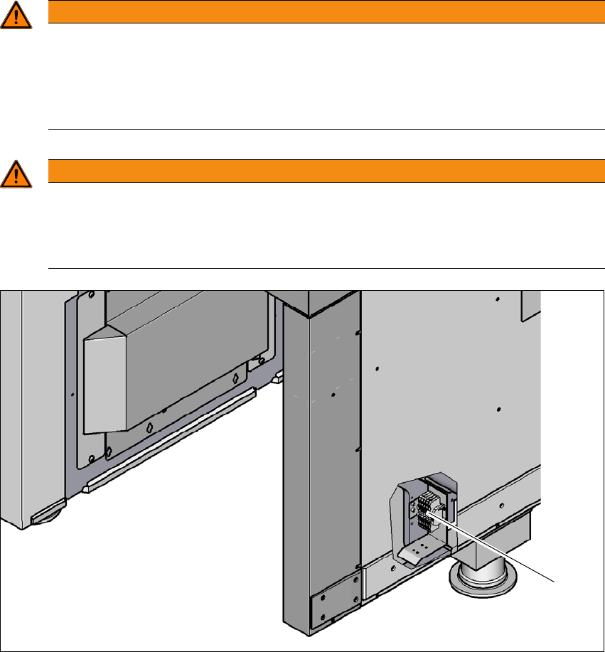
The placement machines features the mains connection cable WITHOUT connector plug. 4
4
Fig. 4.4 - 5 Description of wires in the mains power cable
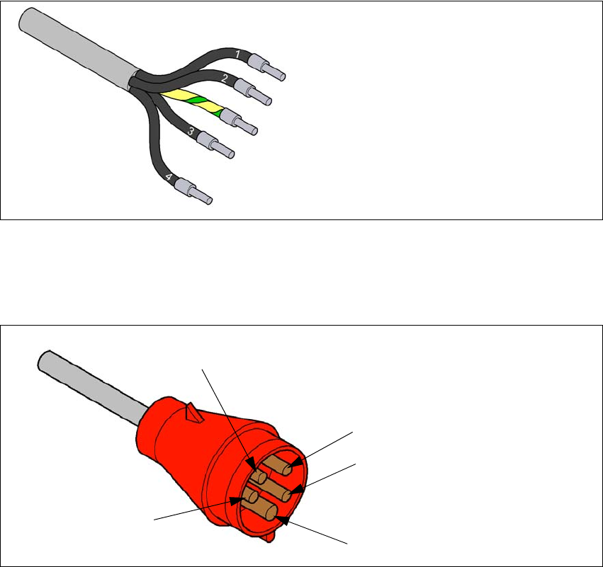
– The machine is configured for voltages of 3 x 360 V~ to 3 x 415 V ± 10 %, 50/60 Hz.
The placement machine has a mains power cable WITH a 16A Cekon plug. 4
4
Fig. 4.4 - 6 Assignment in the Cekon plug
1 = (L1): three-phase
2 = (L2): three-phase
3 = (L3): three-phase
4 = (N): neutral conductor
green/yellow = (PE): conductor
PE
L1
L2
L3
N