00198442-01_UM_TX-V2_EN.pdf - 第180页
4 Setting up and commissioning User manual SIPLACE TX V2 4.5 Setting up the placement machine From software version 711.1 04/2018 180 4.5.4 Removing the corrosion pr otection from the guide rails The placement machines w…

User manual SIPLACE TX V2 4 Setting up and commissioning
From software version 711.1 04/2018 4.5 Setting up the placement machine
179
4.5.3.2 Fitting the shipping brace on the Y axis again
The shipping brace on the Y axis fastens the gantry to the machine frame.
See also fig. 4.5 - 2
, page 177).
Unscrew the counternut 20 to 30 mm from the outer end of the long thread of the shipping
brace.
Push the gantry away from the buffer of the end position stop.
Screw the shipping brace with the long thread approx. 20 mm into the buffer plate (the thread
should protrude from the back by approx. 10 mm).
Carefully pull the gantry towards the short thread end of the shipping brace.
Screw the short thread into the hole on the gantry, as far as the stop.
Use a size 13 fork wrench to hand-tighten the shipping brace on the long hexagon.
Turn the counternut towards the buffer plate on the end position stop.
Hand tighten the counternut.

4 Setting up and commissioning User manual SIPLACE TX V2
4.5 Setting up the placement machine From software version 711.1 04/2018
180
4.5.4 Removing the corrosion protection from the guide rails
The placement machines were given a corrosion protection treatment before they were delivered.
4
4
CAUTION
Reduced product life of bearings and guide rails!
If the corrosion protection agent is mixed with the bearing grease on the axes this can
greatly reduce the service life of the bearings and guide rails.
You should therefore remove the corrosion protection from all the axes and bearings
when you traverse the machine axes for the first time during commissioning. Do not
use any solvents
Wipe all axes and bearings with a SIPLACE cleansing tissue.
CAUTION
Risk of damaging bearing grease!
Alcohol will damage the bearing grease in the guide carriages.
When cleaning the guide rails and scales, make sure that alcohol does not get into
the guide trolley.
User manual SIPLACE TX V2 4 Setting up and commissioning
From software version 711.1 04/2018 4.5 Setting up the placement machine
181
4.5.5 Positioning the placement machine in the line
In order to place the placement machine in a line or lift it out of a line, you must be able to lift the
placement machine at the locations. To so this, you MUST use a pallet truck which complies with
the specifications (see section 4.5.5.3
, page 184) (not a fork-lift!). The center of placement ma-
chine gravity is outside the placement machine center (see section 3.3.3
, page 105). Steel spac-
ers at the locations for limiting the fork position (item 2 in fig. 4.5 - 3
, page 181) ensure that the
pallet truck can be optimally positioned and therefore compensate the eccentric center of place-
ment machine gravity.
4
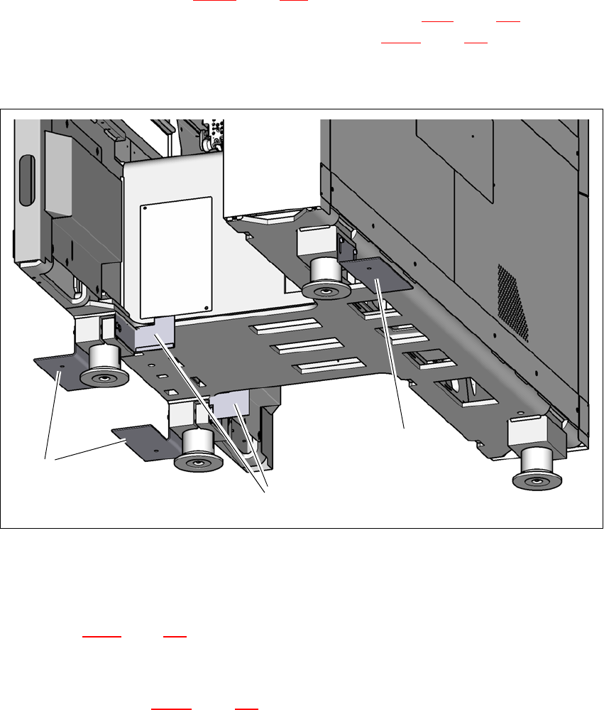
Fig. 4.5 - 3 Steel spacers at the locations to limit the fork position
(1) Shipping braces with steel spacer
(2) Steel spacers to limit the fork position of the pallet truck
The diagram 4.5 - 4
, page 183 shows the fork-lift attachment points on the placement machine for
placing the placement machine in a line or lifting it out of a line.
If not present, now remove the shipping braces and steel spacers from the placement ma-
chine (item 1 in fig. 4.5 - 3
, page 181).
Keep the shipping braces for later use.
(2)
(1)
(1)