00198442-01_UM_TX-V2_EN.pdf - 第194页
4 Setting up and commissioning User manual SIPLACE TX V2 4.6 Adjusting the component trolley to the PCB conveyor height From software version 711.1 04/2018 194 4.6.1 W arning instructions 4 4.6.2 T ools and eq uipment Y …
User manual SIPLACE TX V2 4 Setting up and commissioning
From software version 711.1 04/2018 4.6 Adjusting the component trolley to the PCB conveyor height
193
4.6 Adjusting the component trolley to the PCB conveyor
height
The component trolley can be easily and quickly adjusted to the following PCB conveyor heights:
900 mm 4
930 mm (standard height) 4
950 mm 4
4
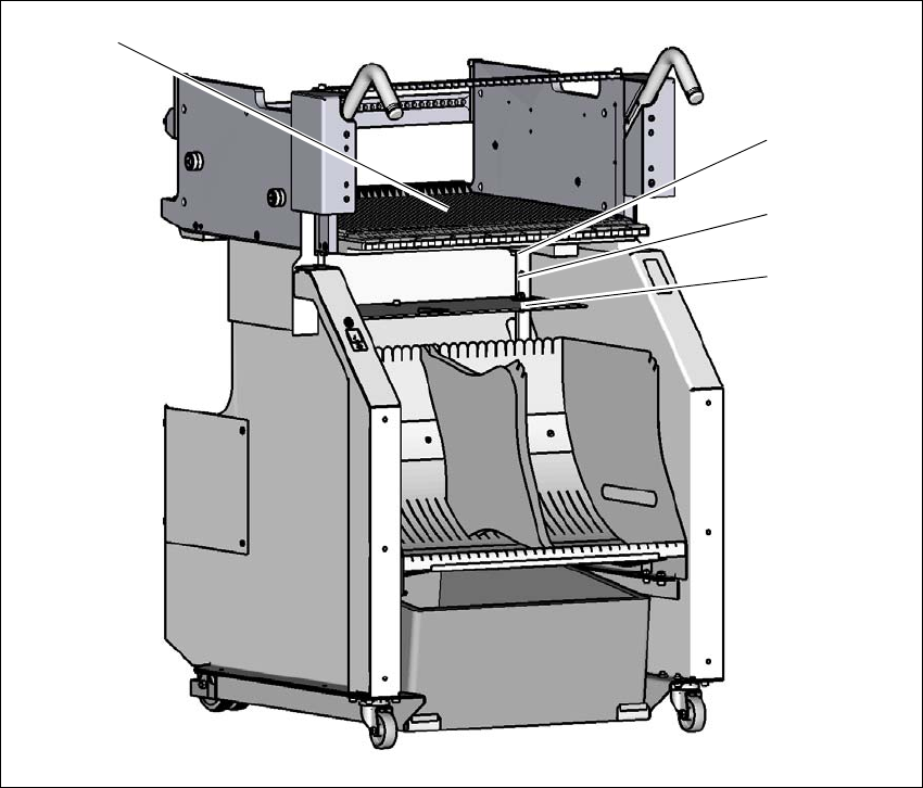
Fig. 4.6 - 1 Component trolley
(1) Holes for the transport heights of 900, 930 and 950 mm.
(2) Changeover table
900 mm
930 mm
950 mm
(1)
(2)
4 Setting up and commissioning User manual SIPLACE TX V2
4.6 Adjusting the component trolley to the PCB conveyor height From software version 711.1 04/2018
194
4.6.1 Warning instructions
4
4.6.2 Tools and equipment
You will need the following tools and equipment to adjust the height of the component trolley:
– Fit-up aid (item no. 03015976-xx)
– Lifting device for raising the component trolley table, carrying capacity at least 80 kg
4.6.3 Changing the component trolley height
4
Fix the fit-up aid to the changeover table with the two M8 x 50 hexagon socket head screws.
Hook the leverage device into the eyelet.
Loosen the fixture pin and lift the changeover table into the required position.
Insert the fixture pin into the hole for the required height.
Dismantle the fit-up aid.
WARNING
Adjustment of component trolley height by certified persons!
Only ASM Assembly Systems GmbH&Co.KG engineers or qualified personnel are per-
mitted to adjust the component trolley height.
Always follow the applicable accident prevention regulations.
Remove all the feeder modules from the changeover table, if you want to adjust the
height of the changeover table.
WARNING
Risk of damage!
Lifting and lowering the changeover table can lead to deformation of it.
Remove all the feeder modules from the changeover table.
Fit the fit-up aid to the changeover table in order to adjust the height.

User manual SIPLACE TX V2 4 Setting up and commissioning
From software version 711.1 04/2018 4.7 Commissioning the placement machine
195
4.7 Commissioning the placement machine
4.7.1 Commissioning the placement machine at the customer's premises
Check all modules for correct seating.
Remove the shipping braces (see section 4.5.2, page 176).
Wipe the linear guide rails of the X/Y axis with a lint-free cloth. Do not use any solvents (see
section 4.5.4
, page 180).
Connect the power and compressed air supplies. Make sure that the incoming leads and ca-
bles can not be tripped over. If possible, run the incoming cables under the placement ma-
chine.
Switch the placement machine on and check the function of the safety features such as the
EMERGENCY STOP button, position switch for covers and the component trolley.
Perform a reference run.
Perform initial calibration of the placement machine (see section 4.7.2.1, page 196).
Load a recipe in the computer and test it.
Check the machine zero point after a period of warming up of 3 - 4 h.
Get the customer's operating personnel to equip the feeder modules according to the cus-
tomer's placement program.
Instruct them in handling the feeder modules using the JobGuide.
4.7.2 Checking and setting the protective cover switch
Check the function of the protective cover switch (see 2.4.1 on page 63).
Adjust the protective cover switch if necessary (see service manual).