00198442-01_UM_TX-V2_EN.pdf - 第204页
5 Tasks at the placement machine User manual SIPLACE TX V2 5.2 Controls and displays From software version 711.1 04/2018 206 5.2.2 Description All the contr ols can be reached by a 1.40 m tall pers on. Main switch 5 The …
User manual SIPLACE TX V2 5 Tasks at the placement machine
From software version 711.1 04/2018 5.2 Controls and displays
205
5.2 Controls and displays
5.2.1 Overview
5
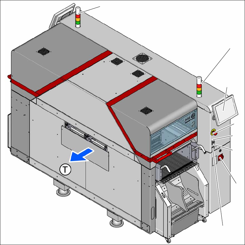
Fig. 5.2 - 1 Controls and displays (location 2)
5
(1) Multitouch monitor (5) Main switch
(2) EMERGENCY STOP button (6) Button for docking and undocking the
component trolley
(3) Start button (green) (7) Indicator lamps with horn
(4) Stop button (black) (T) Direction of PCB transport
(6)
(2)
(4)
(3)
(1)
(7)
(7)
(5)

5 Tasks at the placement machine User manual SIPLACE TX V2
5.2 Controls and displays From software version 711.1 04/2018
206
5.2.2 Description
All the controls can be reached by a 1.40 m tall person.
Main switch 5
The main power switch is used to switch the power supply to the placement machine on and off.
5
Stop button (black) 5
These buttons are used to stop the placement machine. The mechanical closure on the protective
cover lock is released and the covers can be opened.
Start button (green) 5
This green button starts the placement machine after it has been switched on or after faults have
been eliminated.
EMERGENCY STOP button 5
The EMERGENCY STOP button latches in the ON position when pressed. The power supply to
the gantry axes, conveyors and cutters is interrupted and the voltage supplied to the star axes of
the placement heads is reduced. Turn the button to release it.
Multitouch monitor 5
On each side of the placement machine, there is a flat screen with a highly sensitive "multi-touch"
surface (screen with multi-finger gesture recognition). Use the station software to show a key-
board for screen entries.
Indicator lamp with horn - three color (standard) 5
The sequence of colors of the indicator lamps is red - yellow - green. These lamps are used to
signal operating statuses and malfunctions of the placement machine. See also Section 5.7 on
page 224.
Indicator lamp with horn - two color (option) 5
The sequence of colors of the indicator lamps is white - green. These lamps are used to signal
operating statuses and malfunctions of the placement machine. See also Section 5.7 on page
224.
DANGER
Lethal voltages!
Some parts inside the placement machine carry potentially lethal voltages - even when
switched off at the main power switch.

User manual SIPLACE TX V2 5 Tasks at the placement machine
From software version 711.1 04/2018 5.3 Switching on the SIPLACE line
207
5.3 Switching on the SIPLACE line
5.3.1 Starting the SIPLACE Pro Line Control GUI program
Start the program on the line computer SIPLACE Pro Line Control GUI
via the Windows Start menu
Start --> Programs --> SIPLACE Pro --> LCGUI
or
with the icon on your desktop.
Enter your user data.
The system connects to the SIPLACE Pro server and opens the user interface.
5.3.2 What to consider before switching on the stations
5
Check whether the stations are connected to the power and compressed air supplies.
Perform a sight check of the stations. Make sure that there are no obstacles in the travel
range of the gantries.
Make sure that the Z axes of all heads are in their uppermost end positions.
5.3.3 Switching on the station and starting the station software user interface
Switch the station on at the main power switch.
After switching on, check whether the manometers show the required operating pressure.
The station computer software is loaded and the "Production" view of the station software is
shown for the "Production" operator level (see following diagram).
CAUTION
Before you switch on the stations, please perform the following steps.