00198442-01_UM_TX-V2_EN.pdf - 第74页
2 Operational safety Use r manual SIPLACE TX V2 2.5 Safety features From software version 711.1 04/2018 74 2.5.2.2 Position of the position switches on the pl acement machine 2 Fig. 2.5 - 4 Position of the position switc…
User manual SIPLACE TX V2 2 Operational safety
From software version 711.1 04/2018 2.5 Safety features
73
2
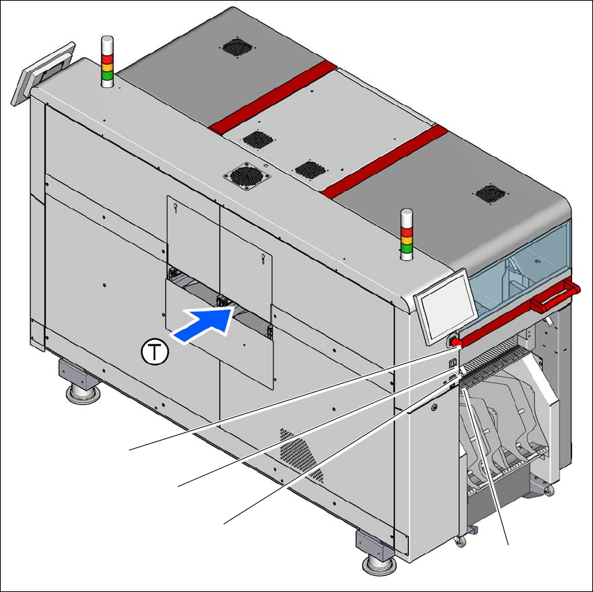
Fig. 2.5 - 3 Position of switches and buttons - PCB input end (location 1)
(1) EMERGENCY STOP button
(2) Start button (green)
(3) Stop button (black)
(4) Button for docking and undocking the component trolley at the respective location
(T) PCB transport direction
(3)
(1)
(4)
(2)
2 Operational safety User manual SIPLACE TX V2
2.5 Safety features From software version 711.1 04/2018
74
2.5.2.2 Position of the position switches on the placement machine
2
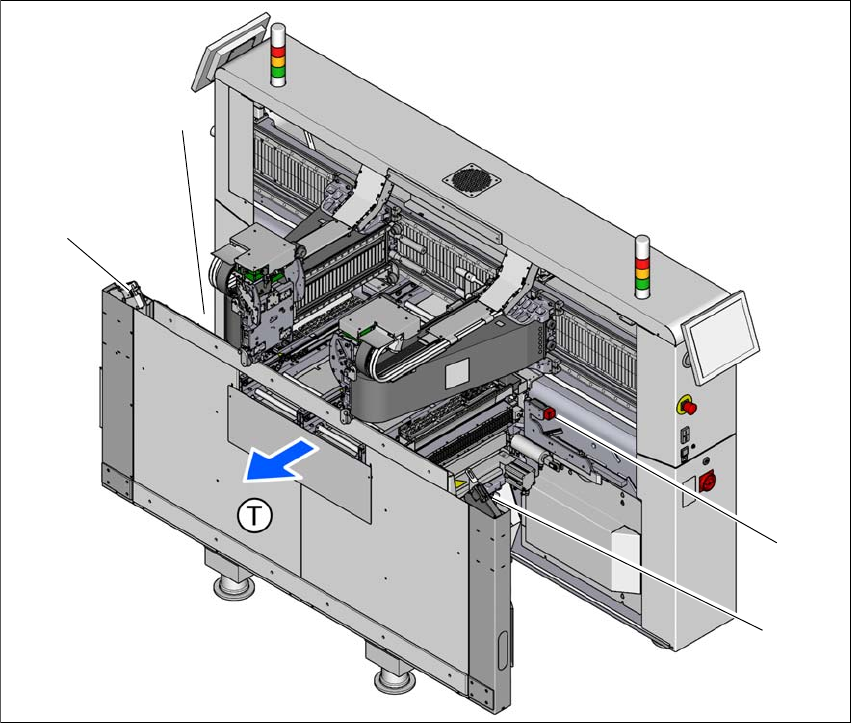
Fig. 2.5 - 4 Position of the position switches
(1) Position switches, location 1
(2) Protective switch for COT insert, location 1
(3) Protective switch for COT insert, location 2
(4) Position switches, location 2
The protective covers are mechanically locked during placement machine operation. The protec-
tive covers can only be opened once the stop button has been pressed.
(4)
(1)
(3)
(2)

User manual SIPLACE TX V2 2 Operational safety
From software version 711.1 04/2018 2.5 Safety features
75
2.5.2.3 Description of functions
Main switch in OFF position (see item 1 in fig.
2.5 - 2, page 72) 2
The main power switch disconnects the three phases L1, L2, and L3 from the power supply.
2
Main switch in ON position 2
When the main switch is switched to ON, the mains voltage is switched through and all AC/DC
converters are addressed.
The control computer starts and all supply voltages, with the exception of the intermediate circuit
voltages for the gantry axes (300 V-) and the star axes (160 V-), are made available internally.
Stop button, black (item 2 in fig. 2.5 - 2, page 72 and item 2 in fig. 2.5 - 3, page 73) 2
These buttons are used to stop the placement machine. The mechanical closure on the protective
cover lock is released and the covers can be opened.
DANGER
Incorrect handling of the placement machine can therefore result in death or severe injury
or considerable damage to equipment.
The following components still carry potentially lethal voltages even if the main power
switch is switched off:
– Cable connection terminals L1, L2, and L3 of the Q1 main power switch
– Cable connection terminals X2, X10, X300, F1 and power pack PS5
– It can take up to 2 seconds until the residual voltage from the EMC filter has been
discharged at the power supply plug.
– Safety cutoff (CSB), capacitor bank, power pack PS4 and testing terminals X303 -
X306 remain live for 5 minutes after the main switch has been switched off.
– The color of all individual wires, which are still live, even if the main switch is
switched off, is orange.
Always follow the applicable accident prevention and DIN regulations (particularly
EN 60204, part 1 or IEC 60204, part 1) and the applicable regulations in your own
country.
The safety door to the power supply must ONLY be opened by appropriately quali-
fied and trained personnel.