00198442-01_UM_TX-V2_EN.pdf - 第87页
User manual SIPLACE TX V2 2 Operational safety From software version 711.1 04/2018 2.7 Disabling the compressed air supply and discharging the pressure 87 2.7 Disabling the compressed air supply and discharging the press…

2 Operational safety User manual SIPLACE TX V2
2.6 Residual voltages and discharge times From software version 711.1 04/2018
86
2.6.5 Compressed air conditions after switching off at the main switch
When the main switch is switched off or the mains supply to the placement machine fails, the elec-
trically-controlled main valves of the compressed air unit will close (item 1 in fig. 2.7 - 1
, page 88).
The pressure will drop to 0 MPa (0 bar) within 5 seconds. The components before the electrically-
controlled main valves will remain pressurized.

User manual SIPLACE TX V2 2 Operational safety
From software version 711.1 04/2018 2.7 Disabling the compressed air supply and discharging the pressure
87
2.7 Disabling the compressed air supply and discharging
the pressure
The compressed air unit is at location 2 (see fig. 4.4 - 1, page 166). The compressed air working
pressure of the placement machine is set to 0.51 ± 0.01 MPa (5.1 ± 0.1 bar). The position of the
compressed air unit is shown at item 1 in fig. 2.7 - 1
, page 88. The supply of compressed air to
the placement machine can be interrupted with the shutoff valve (item 2 in fig. 2.7 - 1
, page 88).
Use the placement machine key to release the cover lock.
Lift the cover (see fig. 2.7 - 1, page 88).
Turn the lever of the shutoff valve (item 1 of fig. 2.7 - 1, page 88) from the vertical to the hor-
izontal position.
Monitor the operating pressure manometer (item 5 in fig. 2.7 - 1, page 88). When the place-
ment machine is switched on, the pressure discharges to 0 MPa (0 bar) within 1 minute.
2
CAUTION
Interruption to compressed air supply!
When the placement machine is switched on, do not use the stop valve to interrupt
the compressed air supply for more than 30 minutes.
If you need to shut off the pneumatic system for longer in order to carry out preven-
tive maintenance or servicing work, you must switch the placement machine off at
the main switch and disconnect it from the power supply.
2 Operational safety User manual SIPLACE TX V2
2.7 Disabling the compressed air supply and discharging the pressure From software version 711.1 04/2018
88
2
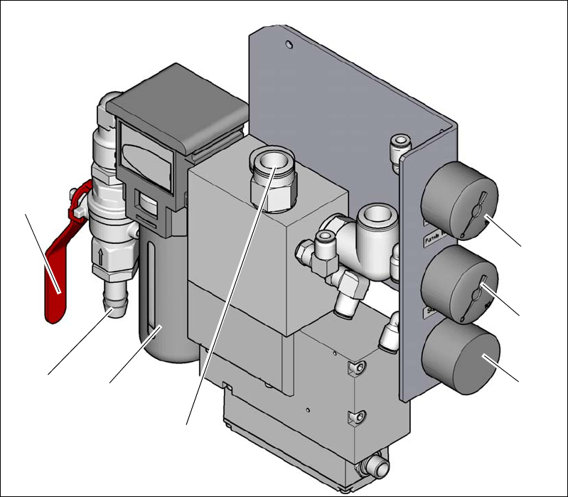
Fig. 2.7 - 1 Compressed air unit on the placement machine
Legend for fig. 2.7 - 1
(1) Manometer for the placement machine component supply pressure
Target pressure: 0.51 ± 0.01 MPa, 5.1 ± 0.1 bar (display range 0 - 1.0 MPa, 0 - 10 bar)
(2) Manometer for supply pressure of gantries 1 to 2
Target pressure: 0.485 ± 0.01 MPa, 4.85 ± 0.1 bar (display range 0 - 1.0 MPa, 0 - 10 bar)
(3) Manometer for inlet pressure
Target pressure: 0.5 - 1.0 MPa, 5 - 10 bar (display range: 0 - 1.0 MPa, 0 - 10 bar)
(4) Compressed air supply for gantries
(5) Compressed air filter
(6) Compressed air connection
(7) Stop valve in the "OPEN" position
(6)
(1)
(2)
(3)
(5)
(7)
(4)