6-2-2-p0723-0782-cxsj_en.pdf - 第14页
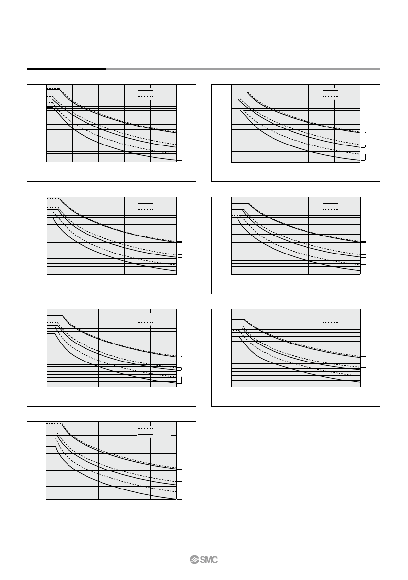
Horizontal Mounting Overhang L (mm) 0 0.1 3 1 20 40 60 80 100 0 0.04 0.1 1 20 40 60 80 100 0 0.03 0.1 1 2 20 40 60 80 100 0 0.06 0.1 1 3 20 40 60 80 100 0 0.04 0.1 2 1 20 40 60 80 100 Load mass m (kg) Load mass m (kg) Lo…
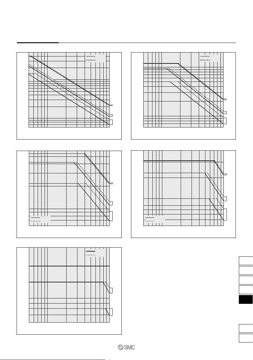
Vertical Mounting
ø32
ø25
ø20
ø20
ø25
ø32
Load mass m (kg)
Load mass m (kg)
Overhang L (mm) Overhang L (mm)
5
0.6
1
6
5
10 20 30 40 50 100
5
1
2
3
0.6
10 20 30 40 50 100
ø32
ø25
ø20
Load mass m (kg)
Overhang L (mm)
5
1
0.6
3
2
10 20 30 40 50 100
Overhang L (mm)
5
10
50
1
0.6
10 20 30 40 50 100
5
1
0.6
10
20
10 20 30 40 50 100
Load mass m (kg)
Load mass m (kg)
Overhang L (mm)
ø32
ø25
ø20
ø32
ø25
ø20
Graph (1) V = 200 mm/s
CXSM
CXSL
Graph (5) V = 1000 mm/s
CXSM
CXSL
Graph (2) V = 400 mm/s
CXSM
CXSL
Graph (3) V = 600 mm/s
CXSM
CXSL
Graph (4) V = 800 mm/s
CXSM
CXSL
Model Selection/With Air Cushion CXS Series
735
CX2
CXW
CXT
CXSJ
CXS
D-
-X
CXS
Horizontal Mounting
Overhang L (mm)
0
0.1
3
1
20 40 60 80 100
0
0.04
0.1
1
20 40 60 80 100
0
0.03
0.1
1
2
20 40 60 80 100
0
0.06
0.1
1
3
20 40 60 80 100
0
0.04
0.1
2
1
20 40 60 80 100
Load mass m (kg)
Load mass m (kg)
Load mass m (kg)
Load mass m (kg)
Load mass m (kg)
Load mass m (kg)
Load mass m (kg)
Overhang L (mm)
Overhang L (mm) Overhang L (mm)
Overhang L (mm) Overhang L (mm)
Overhang L (mm)
0
0.02
0.1
20 40 60 80 100
0
0.02
0.1
1
2
20 40 60 80 100
ø32
ø25
ø20
ø32
ø25
ø20
ø32
ø25
ø20
ø32
ø25
ø20
ø32
ø25
ø20
ø32
ø25
ø20
ø32
ø25
ø20
Graph (6) V = Up to 800 mm/s; Up to 10 st
CXSM
CXSL
Graph (7) V = Up to 1000 mm/s; Up to 10 st
CXSM
CXSL
Graph (8) V = Up to 800 mm/s; Up to 30 st
CXSM
CXSL
Graph (9) V = Up to 1000 mm/s; Up to 30 st
CXSM
CXSL
Graph (10) V = Up to 1000 mm/s; Up to 50 st
CXSM
CXSL
Graph (12) V = Up to 1000 mm/s; Up to 100 st
CXSM
CXSL
Graph (11) V = Up to 1000 mm/s; Up to 75 st
CXSM
CXSL
CXS Series
736
When operating an actuator with a small diam-
eter and a short stroke at a high frequency, the
dew condensation (water droplet) may occur
inside the piping depending on the conditions.
Simply connecting the moisture control tube to
the actuator will prevent dew condensation
from occurring. For details, refer to the IDK s e-
ries in the Best Pneumatics No. 6.
Moisture
Control Tube
IDK Series
Dual Rod Cylinder/Compact Type
ø6, ø10, ø15, ø20, ø25, ø32
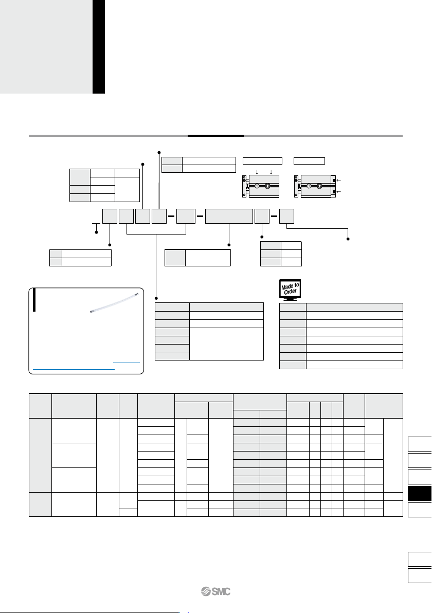
CXSJ Series
How to Order
50 M9BWCXSJ
Compact type
SM P6
Applicable Auto Switches/Refer to pages 1119 to 1245 for detailed auto switch specifications.
∗ Solid state auto switches marked with “
” are produced
upon receipt of order.
24 V
Special functionType
Electrical
entry
Indicator
light
Wiring
(output)
Load voltage
ACDC
Auto switch model
Lead wire length (m)
∗
0.5
(Nil)
3
(L)
5
(Z)
1
(M)
—
—
IC circuit
—
IC circuit
Applicable load
Perpendicular
In-line
IC circuit
—
IC circuit
—
IC circuit
—
Diagnostic indication
(2-color indicator)
Water resistant
(2-color indicator)
Yes
None
Yes
Grommet
Grommet
3-wire (NPN equiv.)
Pre-wired
connector
—
—
—
Relay,
PLC
—
Relay,
PLC
—
— 5 V
12 V
5 V
,
12 V
5 V
,
12 V
12 V
5 V
,
12 V
12 V
5 V
,
12 V
12 V
24 V
A96V
A93V
∗
2
A90V
A96
A93
A90
—
100 V
100 V or less
—
—
2-wire
3-wire (NPN)
3-wire (PNP)
2-wire
3-wire (NPN)
3-wire (PNP)
2-wire
3-wire (NPN)
3-wire (PNP)
2-wire
—
—
M9NV
M9PV
M9BV
M9NWV
M9PWV
M9BWV
M9NAV
∗
1
M9PAV
∗
1
M9BAV
∗
1
M9N
M9P
M9B
M9NW
M9PW
M9BW
M9NA
∗
1
M9PA
∗
1
M9BA
∗
1
Nil
TN
TF
Port thread type
M thread
Rc 1/8
NPT 1/8
G 1/8
ø6 to ø25
ø32
M
L
Bearing type
Slide bearing
Ball bushing bearing
Nil
P
Piping
Standard (ø6 to ø32)
Axial (ø6, ø10)
Port location
Standard piping
Axial piping
Port
location
Made to Order
(Refer to the below.)
Nil
S
n
Number of auto switches
2 pcs.
1 pc.
“n” pcs.
Bore size
6
10
15
20
25
32
Bore size/Stroke
Standard stroke
10, 20, 30, 40, 50
10, 20, 30, 40, 50, 75
10, 20, 30, 40, 50, 75, 100
(mm)
-XB6
-XB11
Note 1)
-XB13
-XC6
Note 2)
-XC19
-XC22
-XC85
Heat resistant cylinder (–10 to 150°C)
Long stroke type
Low speed cylinder (5 to 50 mm/s)
Made of stainless steel
Intermediate stroke (spacer)
Fluoro rubber seals
Grease for food processing equipment
Symbol
Specifications
Made to Order
Click here for details
Note 1) Except ø6, Axial type
Note 2) Slide bearing type (M) only
Solid state auto switch
Reed
auto switch
∗1 Water resistant type auto switches can be mounted on the above models, but in such case SMC cannot guarantee water resistance.
Consult with SMC regarding water resistant types with the above model numbers.
∗2 1 m type lead wire is only applicable to D-A93.
∗ Lead wire length symbols: 0.5 m ·················· Nil (Example) M9NW
1 m ·················· M M9NWM
3 m ·················· L M9NWL
5 m ·················· Z M9NWZ
• Since there are applicable auto switches other than listed, refer to page 747 for details.
• For details about switch with pre-wired connector, refer to pages 1192 and 1193.
∗ Auto switches are shipped together (not assembled).
Nil
Auto switch
Without auto switch
(with built-in magnet)
∗ Refer to the below table for auto
switch model numbers.
737
CX2
CXW
CXT
CXSJ
CXS
D-
-X
CXSJ
D